isweek GM63B Instruction Manual Download Page 20

-18-

200

400

600

800

1K

-20

-15

-10

-5

0

5

-10

-5

0

5

0

5

10

15

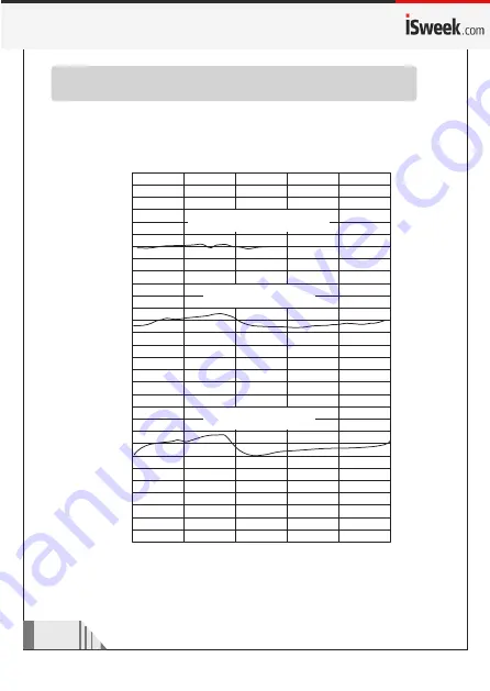
Contact resonance in acceleration measurement:
(worked  with FFT signal analyzer)

R

e

s

p

o

n

s

e (

d

b

)

Without Accessory

Accessory  S

Accessory  L

Frequency(Hz)

LO range    


(Measured with FFT Signal analyzer)

Summary of Contents for GM63B

Page 1: ...Vibration Meter Instruction Manual ON MEAS...

Page 2: ...be tip 08 Connection between handle and main unit 09 Turn on the unit and check up battery 10 Select measurement mode 11 Select high low frequency 12 Measuremen t 13 Maxmum value measurement 15 Temper...

Page 3: ...probe accessorg S Equiped on the main unit Magnetic probe PP packing box Check up 1 Before use Carefully unpack your kit and ensure that you have the following items In case that any item is missing o...

Page 4: ...nufacture electric power meta llurgy and general aviation etc Field LCD display measurement result and conditions directly 2 Measures acceleration m s peak velocity mm s ms and displacement mm p p Sel...

Page 5: ...temperature range Operating humidity range Low battery indication Dimensions Weight Temperature range Temperature accuracy Technical specification Piezoelectric ceramic accelerometer shear type 2 0 1...

Page 6: ...Vibration Meter HI LO A V D ON MEAS MAX C F ON MEAS 1 5 6 8 9 2 3 4 7 04 Diagram of the unit...

Page 7: ...tion 5 Maximum value locks botton 6 Temperature unit interchange botton 7 Measuring mode Acceleration Velocity Displacement select bottom 8 Handle on off measure button press for turn on In measuring...

Page 8: ...display 7 Temperature unit display for the Celsius scale for the Fahrenheit scale 8 When measuring acceleration LCD will display 2 acceleration unit m s When measuring velocity LCD will display veloci...

Page 9: ...t body with your left hand hold down the battery door with your right hand thumb to open it according to the arrow referring direction b Insert the 9V battery into battery compartment note the battery...

Page 10: ...obe tip L Suitable for narrow object or special objects to obtain quick response as the following at figure ON MEAS C With Magnetic probe Suitable for measurement in cases where flat Ferric object to...

Page 11: ...ame direction Main unit plug Handle plug Before use plug in the handle to main unit s socket the same direction there a lock sound to ensure the plug is locking When plug out the user must push the me...

Page 12: ...ess Press 1 Press the on the main unit or on the handle to turn on as shown in following figure 2 After the entire screen displays for 1 second the default state is acceleration mode if on the LCD dis...

Page 13: ...he measuring mode the default 2 status is accelerometer measure m s as following picture 2 Press the key one times to selecting speed mea suring mode mm s as following picture 3 Press the key one more...

Page 14: ...y for acceleration measure mode Press key to select the high frequency measure or low frequency measure As following picture Low frequency measuring 10Hz 1kHz Caution High frequency measuring is only...

Page 15: ...corresponding measurement mode Acceleration Velocity Displacement and frequency HI LO holding press the main unit or handle s button press the handle sensor head against the surface with 500g 1kg vert...

Page 16: ...tion 2 Probe tip L is only for low frequency measure when meas ure acceleration if the frequency is over 1 kHz please change Probe tip S for measurement 3 When measurement mode from acceleration in hi...

Page 17: ...e mode In maximum value measuring status the current vibration data and the maximum value will display on LCD display Show as below Maximum vibration value Current Vibration value When press key again...

Page 18: ...16 C F m s m s Temperature unit change In operation press to select Celsius scale and Fahrenheit scale show as below Celsius scale Fahrenheit scale...

Page 19: ...100 50 30 20 10 5 3 2 1 2 5 10 20 50 0 5 0 3 0 2 0 1 30 3 D i s p l a c e m e n t 3 1 0 m m Velocity mm s rms Vibration conversion chart Frequency Hz 5 1 0 4 1 0 3 1 0 2 1 0 1 1 0 3 1 0 4 1 0 2 1 0 10...

Page 20: ...20 15 10 5 0 5 10 5 0 5 0 5 10 15 Contact resonance in acceleration measurement worked with FFT signal analyzer Response db Without Accessory Accessory S Accessory L Frequency Hz LO range Measured wi...

Page 21: ...19 25K 20 15 10 5 0 5 10 5 0 5 0 5 10 15 20K 15K 10K 5K Response db Without Accessory S Accessory L Accessory Frequency Hz HI range...

Page 22: ...achinery proceed with utmost care to prevent accidents due to getti ng caught in the machinery 3 Other items Attentions Caution If the unit shook excessively the receiver may produce extremely high so...

Page 23: ...t required for extended periods of time in order to avoid damage to the battery compartment and the erosion resulting from a battery leakage 2 Do not store or use the unit in following circumstances a...

Reviews: