IS31SE5117 EVB User Manual
Lumissil Microsystems – www.lumissil.com
28
Rev. B, 10/25/2020
10. Sliders
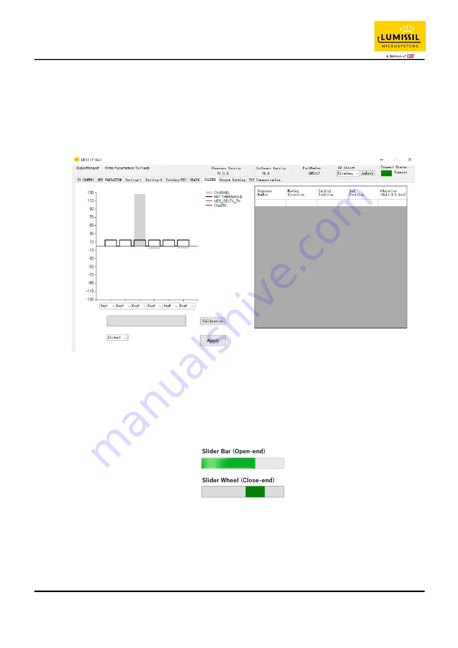
As shown in the blue box in Figure 41, black line is key threshold value, gray line is key value.
When the selected key is combined to the slider (Set the slider type through the IO CONFIG page in Figure 13).
The keys used as a slider will be updated as the finger moves. On the right-hand side of Figure 41,slider’s
information will be updated immediately while sliding.
Sliding keys can also change the order. As shown in the red box below, the key sequence is Key5 to Key10.
Users can change the order of slider keys as needed.
Note: The number of Sliding keys must be 6 keys to be combined.
Figure 41: Slider page of GUI
10.1 Slider Type
As shown in Figure 42 below, Users can set the following slider types (Set the slider type through the IO CONFIG
page in Figure 13).
Slider Bar (Open-end): Used in Slider Board (As shown on the left side of
Error! Reference source not found.
).
Slider Wheel (Close-end): Used in Wheel Board (As shown on the right side of
Error! Reference source not
found.
).
Figure 42: Slider Bar (Open-end) and Slide Wheel (Close-end)
10.2 Slider Key Calibration (Not yet to finish)
When the user develops the slider PCB (Slider Bar or Slider Wheel), the calibration button can be used to
calibrate the moving distance of the slider. When the calibration button is pressed, as shown in the blue box in
Figure 43, the red blocks will be displayed in order. The user must move the slider with a finger at a constant
speed until the red blocks are displayed to the end.


