


How to Install the ISONAS IP-Enabled Reader-controller
26
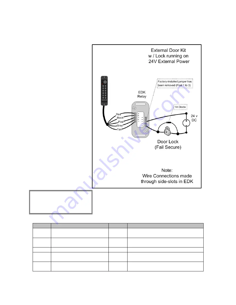
The 2
nd
example shows powering the EDK with the Reader-controller’s PoE power
output, and the lock with an external 24 volt power supply. See
Figure 13
Understanding the
EDK’s LEDs:
When the EDK Power LED
is lit, it indicates that
power is available to the
EDK (Red LED).
The EDK communication’s
LED has four states:
Off
: No signal received
from the reader-controller.
Green
: Signal received
from the reader-controller,
and valid encryption key is
available.
Red
: Signal received from
the reader-controller, but
no encryption key is
available.
Amber
: Communications
problem. May relate to
Pink/Gray/Tan wire
connections or be a
BackEMF issue.
Figure 13
Label Reader Side Connection
Label
Lock Side Connection
R
Pigtail’s Red wire
(12 V Input Power)
1
Not Used
B
Pigtail’s Black wire
(Ground)
2
Not Used
P
Pigtail’s Pink wire
3
EDK Relay’s Common Contact
G
Pigtail’s Gray wire
4
EDK Relay’s Normally Closed (NC)
contact (Fail-Safe Lock)
T
Pigtail’s Tan wire
5
EDK Relay’s Normally Open (NO)
contact (Fail-Secure Lock)
Installation Tip:
Configure the Jumper Blocks
as shown in previous
example
Summary of Contents for powernet
Page 15: ...How to Install the ISONAS IP Enabled Reader controller 15 Power Options Figure 4 ...
Page 40: ...How to Install the ISONAS IP Enabled Reader controller 40 2 3 4 PoE MAGNETIC LOCK Figure 24 ...
Page 43: ...How to Install the ISONAS IP Enabled Reader controller 43 2 3 7 DUAL POWER SOURCES Figure 27 ...


