


How to Install the ISONAS IP-Enabled Reader-controller
24
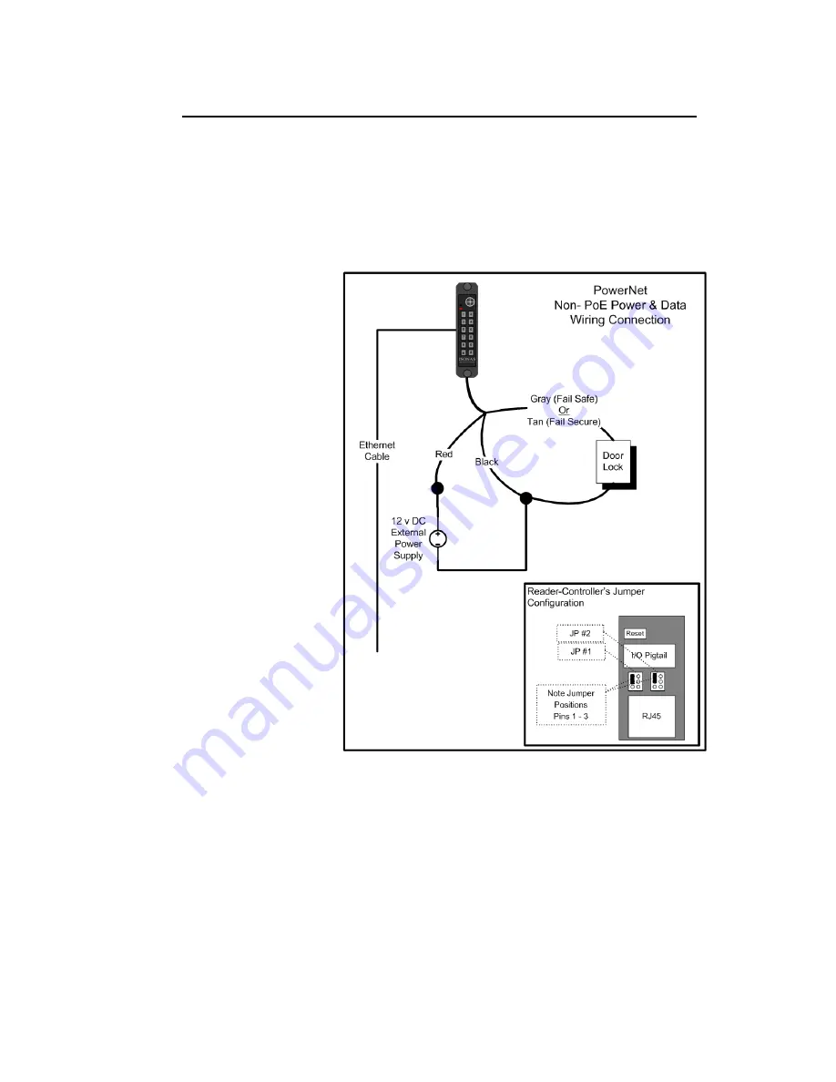
2.2.6: LOCK WIRING -- LOW-VOLTAGE 12VDC POWER OPTION
Powering the reader-controller using low-voltage DC:
Wiring DC power to a Reader-controller:
Simply run the positive and negative
wires from the power source to the positive and negative wires on each Reader. The
example below shows the typical power connection for a reader-controller and a lock.
1.
Connect the positive power from the power supply to the positive power
connection (red lead) of the reader-controller. Install the Jumper pins as
shown, which provides
12VDC to the lock
circuit.
2.
Connect one side of
the electric lock to
EITHER the Tan (Fail
Secure) or Gray (Fail
Safe) connection on
the reader-controller
.
See BackEMF diode or
In-Rush suppressor
sections for more info.
3.
Connect the negative
power from the power
supply to the negative
power connection
(black lead) of the
reader-controller and
the remaining side of
the electric lock.
Figure 11
shows how to
take the power from the
External Power supply and
drive both the PowerNet
Reader-Controller and an
Electronic lock.
Figure 11
Summary of Contents for powernet
Page 15: ...How to Install the ISONAS IP Enabled Reader controller 15 Power Options Figure 4 ...
Page 40: ...How to Install the ISONAS IP Enabled Reader controller 40 2 3 4 PoE MAGNETIC LOCK Figure 24 ...
Page 43: ...How to Install the ISONAS IP Enabled Reader controller 43 2 3 7 DUAL POWER SOURCES Figure 27 ...


