9E
4.2 Main Function
To select any of the pre-set functions, press the
MENU
button up to when the required one is
shown on the display. Select the function by
ENTER
button and the display will blink. Use
DOWN
and
UP
button to change the mode. Once the required mode has been selected,
press the
ENTER
button to setup or it will automatically return to the main functions without
any change after idling 8 seconds. To go back to the functions without any change press the
MENU
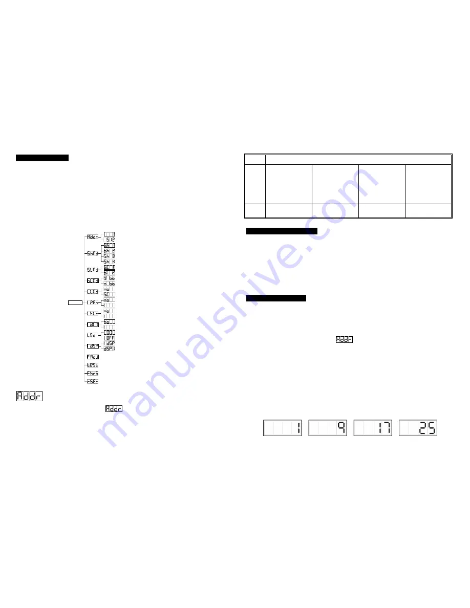
button. The main functions are shown below:
MENU
Focus Adjust
Self-Test
Reset
Fixture Hours
Display Inversion
Display Normal
Tilt Inversion
Tilt Normal
Pan Inversion
Pan Normal
Split Color
Normal Color
Show mode 4
Show mode 3
DMX512 Address Setting
Blackout Mode " No Blackout "
Blackout Mode " Yes Blackout "
Slave Mode " Normal "
Slave mode " 2 Light Show "
Show mode 1
Show mode 2
LED off
LED on
Dimmer Normal
Dimmer Inversion
DMX512 Address Setting
Press the
MENU
button up to when the
is showing on the display. Pressing
ENTER
button and the display will blink. Use
DOWN
and
UP
button to change the DMX512 address.
Once the address has been selected, press the
ENTER
button to setup or automatically
return to the main functions without any change after 8 seconds. To go back to the functions
without any change press the
MENU
button again.
Stand by Blackout the unit
Function
Strobe
1.Gobo/Color sync.
strobe
2.Sync. strobe
3.Two-light strobe
X/Y moving show
mode selection
( Show 1 ~ Show 4 )
Please refer to Show
mode in 4.2 Main
Function.
Color/Gobo selection
1. Hold on for gobo
change.
2. Press shortly for
color change.
X/Y moving setting
1.Pan position
2.Tilt position
3.Dimmer
First set Master unit,
then set Slave units’
position.
Mode
Sound 1
(LED off )
Sound 2
(LED normal blinking)
Slow/Sound 3
(LED on)
Position/ Latch
(LED fast blinking)
5.3.1 iSolution Operation
♦
Consistent DMX configuration enable iMove to be linked together with iRock and iShow
and controlled at the same time.
♦
DMX address can be set remotely by iLead controller ( please refer to the user manual
of iLead controller ). No need to calculate the DMX channels of each fixture in the chain.
♦
Automatic switching between DMX function and built-in stand alone programs.
5.3.2 DMX Controller
An universal DMX controller to control the units, you have to set DMX address from 1 to 512
channel so that the units can receive DMX signal.
Press the
MENU
button up to when the
is showing on the display. Pressing
ENTER
button and the display will blink. Use
DOWN
and
UP
button to change the DMX512 address.
Once the address has been selected, press and keep
ENTER
button pressed up to when the
display stops blinking or storing automatically 8 seconds later. To go back to the functions
without any change press the
MENU
button again. Please refer to the following diagram to
address your DMX512 channel for the first 4 units.
DMX address can be setting remotely by IL-0824 controller. No need to calculate the DMX
channels of each fixture in the chain.


