background image

www.isenbergfaucets.com

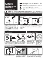
CONNECTING THE WATER LINES


Connect Rigid piping to the input. This will support

the valve

Level Valve

3

INPUT

OUTPUT

The TVH.4511 valve has no temperature

control ability. In order to achieve temper-

ature control ability it should be used in

combination with a temperature control

valve such as the Isenberg TVH.4201.

The image on the left is for illustrative 

purposes only and is by no means the only

connection scenario.

ACCOMPANYING VALVE USAGE

Summary of Contents for THV.4511

Page 1: ...RE YOU BEGIN You must observe all local plumbing laws and codes Do not install this valve if it does not meet local plumbing codes Shut off the main water supply Installation Manual TVH 4511 3 4 Volume Control Use With Trims Ending in 4511 ...

Page 2: ...stem to ensure that no metal swarf solder and other impurities can enter the product Turn off water supply before commencing work Please read these instructions carefully and retain for future reference www isenbergfaucets com TABLE OF CONTENTS Operating Specifications 1 Valve Installation And Tolerance Cut Out Dimensions 1 Rough In Specification 2 Connecting The Water Lines Accompanying Valves 3 Tri...

Page 3: ...g valve PRV This product is to be used with water at a temperature range of 40 F 120 F ONLY www isenbergfaucets com OPERATING SPECIFICATIONS CUT OUT DIMENSIONS Isenbergʼs TVH Series valves comes with a black pre attached mud guard This mud guard is not to be removed or discarded Its purpose is to guide the installation professional on the proper cut out dimensions of the drywall Wall Cut Out Dimen...

Page 4: ...stance between back of the valve to the finished tile surface should be between 2 77 and 3 44 inches Minimum 70 5mm 2 77 Maximum 87 5mm 3 44 2 Finished tile should fall between Min Max If valve is installed too deep into the wall extensions are available ...

Page 5: ...OUTPUT The TVH 4511 valve has no temperature control ability In order to achieve temper ature control ability it should be used in combination with a temperature control valve such as the Isenberg TVH 4201 The image on the left is for illustrative purposes only and is by no means the only connection scenario ACCOMPANYING VALVE USAGE ...

Page 6: ...nsure finished tile surface is between the min and max marks on the mid guards The below diagram shows the markings on the trim plate and the outputs on the valve This will help the installation professional to connect the appropriate accessories to the valve output ports 4 TRIM MARKINGS WATER OUTPUT ...

Page 7: ...you must flush the valve before the wall is closed and water is turned on for the first time 1 Remove cartridge by turning with a spanner 2 Turn on water supply and let water flow removing any dirt in the lines 5 CARTRIDGE CLEANING MAINTENANCE CARTRIDGE CLEANING MAINTENANCE Volume Control Cartridge Check For Dirt ...

Page 8: ... com INSTALLING THE TRIM TRIM PLATE SIZE AND SHAPE MAY VARY ILLUSTRATION ONLY Remove mud guards Insert trim plate Insert adaptor base and tighten 6 Align Trim plate till it is straight Align Trim plate till it is straight ...

Page 9: ...RIM PLATE SIZE AND SHAPE MAY VARY ILLUSTRATION ONLY Insert centering knob screws Insert handle Tighten hex screw insert cover button Make sure the diverter is set to the OFF marking before your begin This photo shows a completely installed trim 7 ...

Page 10: ...www isenbergfaucets com INSTALLING EXTENSIONS TO THE VALVE OPTIONAL Install extension kit 3 Pieces as shown above 8 ...

Reviews: