background image

MD24 / MD28 

– Hardware Description 


8  Connecting the Motor (P2) 

 
The ME542 driver can drive any 2-pahse and 4-pahse hybrid stepping motors. 


8.1  Connections to 4-lead Motors


4 lead motors are the least flexible but easiest to wire. Speed and torque will depend on 
winding  inductance.  In  setting  the  driver  output  current,  multiply  the  specified  phase 
current by 1.4 to determine the peak output current. 


     4-lead Motor Connections 


8.2  Connections to 6-lead Motors


Like  8  lead  stepping  motors,  6  lead  motors  have  two  configurations  available  for  high 
speed  or  high  torque  operation.  The  higher  speed  configuration,  or  half  coil,  is  so 
described  because  it  uses  one  half 

of  the motor’s inductor  windings.  The higher torque 

configuration, or full coil, uses the full windings of the phases. 
 

8.2.1 

Half Coil Configurations 


As  previously  stated,  the  half  coil  configuration  uses  50%  of  the  motor  phase  windings. 
This gives lower inductance, hence, lower torque output. Like the parallel connection of 8 
lead motor, the torque output will be more stable at higher speeds. This configuration is 
also referred to as half chopper. In setting the driver output current multiply the specified 
per phase (or unipolar) current rating by 1.4 to determine the peak output current. 


6-lead motor half coil (higher speed) connections 

Summary of Contents for MD24

Page 1: ...ermany AG D 36124 Eichenzell Bürgermeister Ebert Str 40 49 0 6659 981 700 49 0 6659 981 776 Item no 970317 BE001 Last update 01 2010 MD24 MD28 Microstepping Driver odul Instruction Manual Hardware Description ...

Page 2: ...dware names of the respective companies that are used in our prints are generally subject to trademark or brand or patent protection All rights reserved No part of our prints may either be reproduced in any form print photography or another procedure or processed copied or published by using electronic systems without written permission of isel Manufacturer isel Germany AG Buergermeister Ebert Str...

Page 3: ...7 8 2 1 Half Coil Configurations 7 8 2 2 Full Coil Configurations 8 8 3 Connections to 8 lead Motors 8 8 3 1 Series Connections 8 8 3 2 Parallel Connections 9 9 Power Supply Selection 9 9 1 Regulated or Unregulated Power Supply 9 9 2 Multiple Drivers 10 10 Selecting Microstep Resolution and Driver Output Current 10 10 1 Microstep Resolution Selection 10 10 1 1 MD24 10 10 1 2 MD28 11 10 2 Current S...

Page 4: ...2 13 Sequence Chart of Control Signals 13 14 Protection Functions 14 15 Problem Symptoms and Possible Causes 15 ...

Page 5: ...rent ripple therefore less motor heating is achieved Features Low cost and good high speed torque Optically isolated input signals Pulse frequency up to 300 KHz Automatic idle current reduction 3 state current control technology High resolution Microstepping Suitable for 2 phase and 4 phas motors DIP Switch setting Over voltage and short circuit protection Small size Suitable for a wide range of s...

Page 6: ... technical personnel and with consideration of the regulations of the electrical industry as well as the rules for the prevention of accidents Assembly and employment of the equipment is to be accomplished according to the standards of the declaration of conformity The regulations and limit values kept by the manufacturer do not protect in case of inappropriate use of the equipment The equipment m...

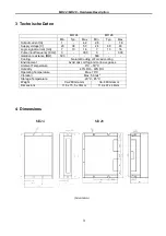
Page 7: ...y KHz 0 300 0 300 Isolation resistance MΩ 500 500 Cooling Natural Cooling or Forced cooling Environment Avoid dust oil fog and corrosive gases Ambient Temperature 0 C 50 C Humidity 40 RH 90 RH Operating Temperature Max 70 C Vibration Max 5 9m s 2 Storage Temperature 20 C 65 C Weight Ca 280 Gramm Ca 440 Gramm Dimensions 118 x 75 5 x 33mm 119 x 97 x 48mm 4 Dimensions MD24 MD28 Draufsicht Seitenansic...

Page 8: ...is signal has low high voltage levels representing two directions of motor rotation in double pulse mode set by inside jumper J2 this signal is counter clock CCW pulse effective for high level or low level set by inside jumper J1 For reliable motion response DIR signal should be ahead of PUL signal by 5µs at least 4 5V when DIR HIGH 0 0 5V when DIR LOW 4 DIR DIR 5 ENA 5V Enable signal This signal ...

Page 9: ...ulse edge or effective level and control signal mode as shown in figure 2 Default setting is PUL DIR mode and upward rising edge effective PUL DIR mode and effective at upward rising edge PUL DIR mode and effective at downward falling edge CW CCW mode and effective CW CCW mode and effective at high level The fixed level at low level The fixed level ...

Page 10: ...c inputs which are located on connector P1 to accept line driver control signals These inputs are isolated to minimize or eliminate electrical noises coupled onto the drive control signals Recommend use line driver control signals to increase noise immunity of the driver in interference environments In the following figures connections to open collector and PNP signals are illustrated a Common ano...

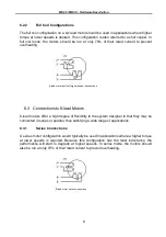
Page 11: ...d or high torque operation The higher speed configuration or half coil is so described because it uses one half of the motor s inductor windings The higher torque configuration or full coil uses the full windings of the phases 8 2 1 Half Coil Configurations As previously stated the half coil configuration uses 50 of the motor phase windings This gives lower inductance hence lower torque output Lik...

Page 12: ...ons 8 3 Connections to 8 lead Motors 8 lead motors offer a high degree of flexibility to the system designer in that they may be connected in series or parallel thus satisfying a wide range of applications 8 3 1 Series Connections A series motor configuration would typically be used in applications where a higher torque at lower speeds is required Because this configuration has the most inductance...

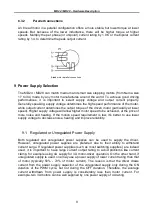
Page 13: ...ed at the price of more noise and heating If the motion speed requirement is low it s better to use lower supply voltage to decrease noise heating and improve reliability 9 1 Regulated or Unregulated Power Supply Both regulated and unregulated power supplies can be used to supply the driver However unregulated power supplies are preferred due to their ability to withstand current surge If regulate...

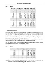
Page 14: ...on and Driver Output Current This driver uses an 8 bit DIP switch to set microstep resolution and motor operating current as shown below 10 1 Microstep Resolution Selection Microstep resolution is set by SW5 6 7 8 of the DIP switch as shown in the following tables 10 1 1 MD24 Microstep Steps rev SW5 SW6 SW7 SW8 2 400 OFF ON ON ON 4 800 ON OFF ON ON 8 1600 OFF OFF ON ON 16 3200 ON ON OFF ON 32 6400...

Page 15: ...g time operation Since parallel and serial connections of motor coils will significantly change resulting inductance and resistance it is therefore important to set driver output current depending on motor phase current motor leads and connection methods Phase current rating supplied by motor manufacturer is important in selecting driver current however the selection also depends on leads and conn...

Page 16: ...this will reduce motor heating to 36 due to P I2 R of the original value 11 Wiring Notes In order to improve anti interference performance of the driver it is recommended to use twisted pair shield cable To prevent noise incurred in PUL DIR signal pulse direction signal wires and motor wires should not be tied up together It is better to separate them by at least 10 cm otherwise the disturbing sig...

Page 17: ...iver power supply and controller pulse generator A typical connection is shown as figure 10 13 Sequence Chart of Control Signals In order to avoid some fault operations and deviations PUL DIR and ENA signals must abide by some rules as shown in the following diagram assuming J1 default setting is upward rising edge effective ...

Page 18: ...turn red When power supply voltage is lower than 22VDC the driver will not works properly Coil ground Short Circuit Protection Protection will be activated in case of short circuit between motor coil and ground Over current Protection only MD28 Protection will be activated when continuous current reaches to 14A Wrong Motor Connection Protection nur MD28 Protection will be activated when the motor ...

Page 19: ... The driver in fault DIP switch current setting is wrong Something wrong with motor coil Control signal is too weak Control signal is interfered Erratic motor motion Wrong motor connection Something wrong with motor coil Current setting is too small losing steps Current setting is too small Motor stalls during acceleration Acceleration is set too high Power supply voltage too low Inadequate heat s...

Reviews: