background image

S p e z i a l e l e k t r o n i k     G m b H


iseg Spezialelektronik GmbH 

Email: [email protected] 

Phone ++ 49 (0)351 / 26 996 - 0 


Bautzner Landstr 23 

http://www.iseg-hv.com 

Fax 

++ 49 (0)351 / 26 996 - 21 


D - 01454 Radeberg / Rossendorf 

Germany 


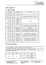
3. PIN assignment 


3.1. Module station 


Connector Description 

Remarks 

+ 5 V 


+ 24 V 


4   c 

I

SL 

Connected to + 24 V with ca. 10 

 / 3 W 

5 a b c 

GND 


 a    CAN_GND 


11  b  

CAN_L 

isolated 

   c  CAN_H 


13 a     

RESET 


OFF with ramp (e.g. 10s after power fail) 


Connector Description 

Remarks 


Bank_addr 

module address b2

4

 , bank switch on front p. 

30 


Bank_addr 

module address b2

5

 , bank switch on front p. 


Mod_addr 

module address b2

2

 , hard-wired 

31 


Bank_addr 

module address b2

3

 , bank switch on front p. 

   c 

GND 


Mod_addr 

module address b2

0

 , hard-wired 

32 


Mod_addr 

module address  b2

1

 , hard-wired 

   c 

GND 


3.2. External CAN-Bus 


The external CAN-Bus to control the iseg 

HV

 module (CAN-

HV

) and the crate with the built-in CAN 

c

rate 

c

ontroller (CAN-

CC

) is connected through RJ45 connectors on the front panel. 

The CAN-Bus standard requires a termination with 120 

 between CAN_L and CAN_H on both ends. For the 

crate side please use the delivered CAN terminations (iseg Art-nr.: 510245 and 580591). 
It is possible to control the HV module and the crate controller via one CAN-Bus (e.g. by connecting “OUT” from 
CAN-HV to “IN” from CAN-CC). 
 

Input Output  PIN  Signal 

  1 

CAN-H 

RJ45 RJ45  2  CAN-L 

  3 

CAN-GND 

Summary of Contents for ECH 238 1200W

Page 1: ...eration Attention It is not allowed to use the unit if the covers have been removed We decline all responsibility for damages and injuries caused by an improper use of the module It is highly recommended to read the manual before any kind of operation Note The information in this manual is subject to change without notice We take no responsibility for any error in the document We reserve the right...

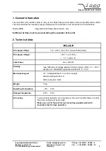
Page 2: ...red during the operation of the unit 2 Technical data ECH 238 M AC supply voltage 110 240 V max 12 A fuses double sided DC supply voltages 24 V up to 50 A 5 V up to 5 A Total Power max 1200 W Floating max difference of voltage between PE and internal GND V 30 V clamped via antiparallel suppressor diode with VZ 56 V Mechanical layout 19 Standard BIN 6 U ca 450 mm depth Module slot depth 220 mm CAN ...

Page 3: ...ront p a Mod_addr module address b22 hard wired 31 b Bank_addr module address b23 bank switch on front p c GND a Mod_addr module address b20 hard wired 32 b Mod_addr module address b21 hard wired c GND 3 2 External CAN Bus The external CAN Bus to control the iseg HV module CAN HV and the crate with the built in CAN crate controller CAN CC is connected through RJ45 connectors on the front panel The...

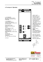
Page 4: ... built in multichannel module with option _SL is active then an output voltage in any channel of it is only present if this safety loop is closed STATUS LED green red green indicates POWER ON 24V DC O K and no CAN error and Option UPS Battery on float charge STDBY AC supply ON remote control possible POWER ON ON OFF switch 24V DC Supply AC Power ECH x38 SL1 SL2 0 CAN HV POWER ON 1 BANK SELECT 2 ST...

Reviews: