ISE Sit-Stand Installation Manual Download Page 7

After the technology has been installed, ensure there is enough slack in the cables from 

the monitor, keyboard and mouse along with any other peripherals.

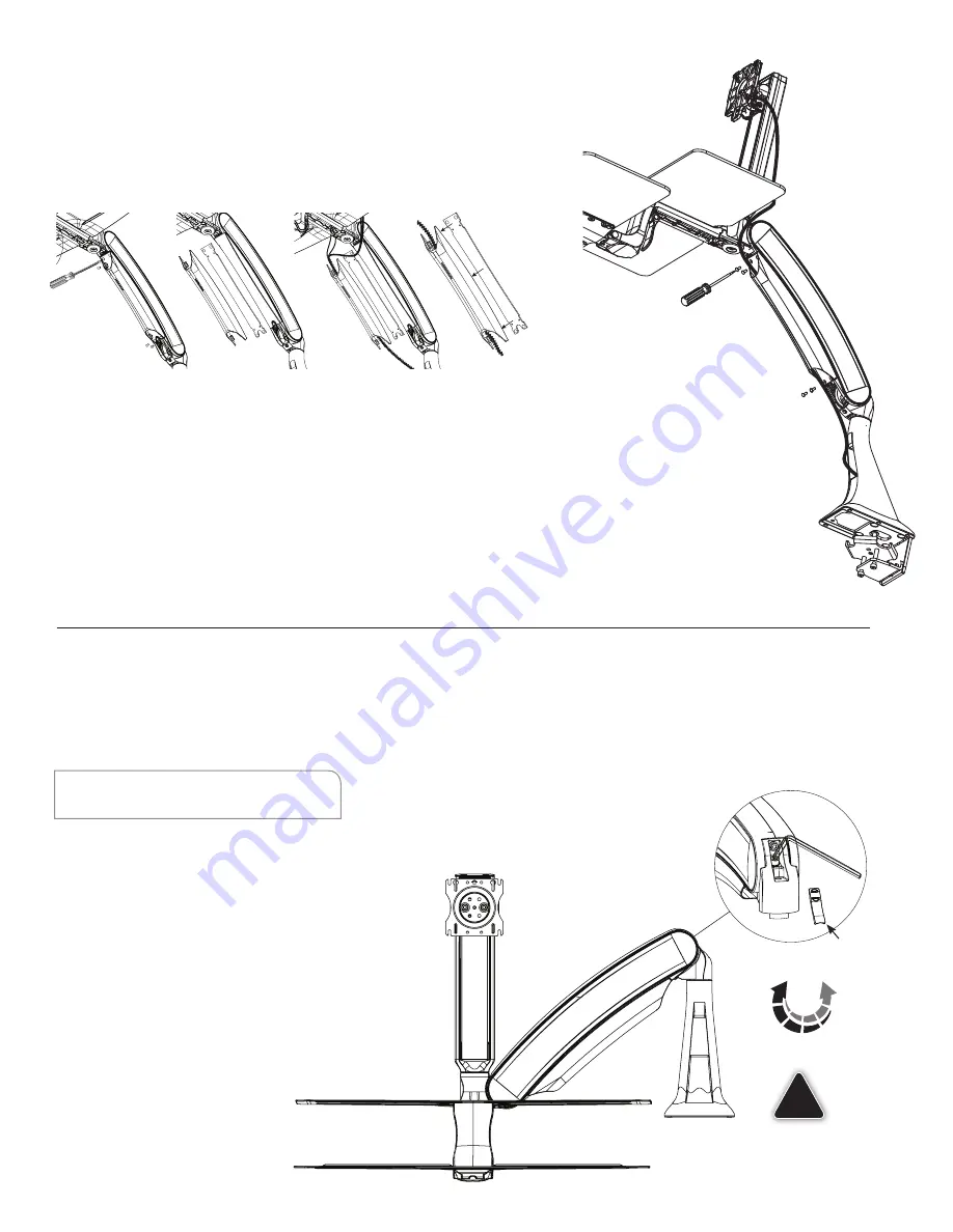
Arm adjustment is to be made after all technology has been installed from 5 lbs. to 20 lbs.

Cable Management Installation

Arm Counterbalance Adjustments

STEP 1

Use a #2 Phillips screwdriver to  

remove the four screws securing  

the cable management tray.

STEP 2

Remove the steel insert from the 

cable management tray. Note 

orientation of steel insert in cable 

management tray.

STEP 3

STEP 6

STEP 7

STEP 1

STEP 2

STEP 5

Re-attach the cable management tray with 

the four #2 Phillips screws removed in STEP 1. 

STEP 6

Cables can be routed through the desk base 

and into the grommet hole if applicable.

STEP 7

Adhesive cable clips are supplied and can be 

used to secure loose cables as required.

STEP 5

STEP 4

STEP 3

Lay all cables (e.g. power, VGA 

and mouse cables) into the cable 

management tray.

STEP 4

Re-assemble steel insert from  

STEP 3 with counter sinks to the  

bottom of the cable management  

tray and notch at the back.

ATTENTION:

Arm must be held down to perform this adjustments.

STEP 1

Remove the trim cap at the back  

of the arm.

STEP 2

Use the 1/4” Allen Key to turn 

the middle bolt at the back 

of the arm. Turning the bolt 

clockwise decreases the spring 

force reducing the counter 

balance load. Turning the bolt 

counterclockwise increases 

the spring force increasing the 

counter  

balance load.

STEP 3

Adjust the middle bolt until the  

arm counter balance is acceptable.

STEP 4

Replace the trim cap at the back  

of the arm.

+

+

+

+

COUNTERBALANCE

ADJUST

Do not overtighten 

bolt as this may cause 

damage to the product.

!

1/4”

Allen Key

STEP 2 & 3

STEP 4

7

Summary of Contents for Sit-Stand

Page 1: ...INSTALLATION MANUAL FOR ACTIVATE SIT STAND WORKSTATION Maximum Load Single Monitor Arm 23 lbs Dual Monitor Arm 19 lbs Monitor Weight Single Monitor up to 20 lbs Dual Monitors up to 8 lbs each...

Page 2: ...ER The manufacturer will bear no responsibility for any damages of any kind arising from improper installation of this product In no way will the manufacturer be held liable for any damage to the moni...

Page 3: ...2 bolts into the bottom clamp Position the clamp plate KIT B Clamp Plate facing up over the tips of the bolts Tighten alternatively each bolt to 75 in lbs with the 7 32 Allen Key to firmly secure the...

Page 4: ...gle bracket to the base Insert the grommet bolt through the washer KIT C Arm Bolt Washer Kit and upward facing clamp plate KIT B Clamp Plate From under the desk insert the grommet bolt assembly throug...

Page 5: ...surface Hand thread each screw into the four holes in the worksurface the nuts have been pre mounted on the underside of the tray support arm and are held in place by the tape STEP 3 Remove the tape...

Page 6: ...ing Quick Connect adapter mount the Quick Connect adapter Kit E VESA Mounting Plate Kit to back of the monitor with the M4 pan head screws provided Use a 2 Phillips screwdriver to secure screws Lift m...

Page 7: ...le STEP 7 Adhesive cable clips are supplied and can be used to secure loose cables as required STEP 5 STEP 4 STEP 3 Lay all cables e g power VGA and mouse cables into the cable management tray STEP 4...

Page 8: ...r Remove cap STEP 2 Remove and install pins as necessary per the drawing while holding the monitor in the highest position If pins are not needed keep them inserted in the bracket hole for possible fu...

Reviews: