


Tools Required / Supplied Part Kits / Warnings/Disclaimer .........2
Possible Base Mounting Orientation
Clamp Mount Base Orientation ........................................ 3
Grommet Mount Base Orientation .................................... 4
Attaching the Arm to the base ................................................. 5
Installing the Work Surface ...................................................... 5
Installing Keyboard Tray .......................................................... 5
Keyboard Tilt .......................................................................... 6
Keyboard Storage Stop ............................................................ 6
Installing the Monitor ............................................................. 6
Cable Management Installation ............................................... 7
Arm Counterbalance Adjustments ............................................ 7
Tray Leveling Adjustments (Left to Right) .................................. 8
Tension Adjustment for the Monitor ......................................... 8
Monitor Tilt Tension Adjustment ............................................... 8
INSTALLATION WARNINGS:
•
Read the entire instruction manual before beginning any installation or assembly.
•
The installer must verify that the attachment surface can safely support the
combined weight of all the attached equipment and hardware.
•
Improper installation of this product may cause extensive property damage
or serious personal injury, either during or after installation.
DISCLAIMER:
•
The manufacturer will bear no responsibility for any damages of any kind
arising from improper installation of this product.
•
In no way will the manufacturer be held liable for any damage
to the monitor, property or personal injury should an outside force either
intentionally or unintentional be applied to the monitor or monitor
mounting bracket
ADJUSTMENT NOTIFICATION:
•
Routine maintenance checks and adjustments are suggested to properly
support the quality and optimal performance of this product.
Refer to adjustment suggestions on last page of booklet, or contact your
distributor for further detailed information.
•
Over tightening of bolts during installation or adjustments can damage
the product and affect the function and warranty.
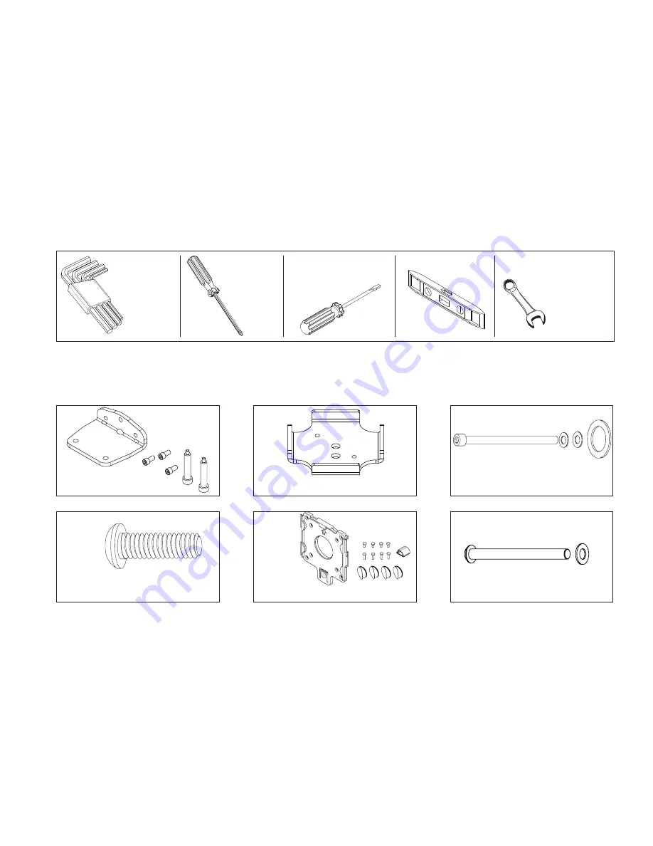
Allen Keys,
1/8",3/16",
7/32",1/4"
(provided)
3/8" Wrench
(for Dual Monitor option)
Tools Required
Supplied Part Kits
#2 Phillips
Screwdriver
Slotted
Screwdriver
Level
Warnings/Disclaimers
KIT A: Bottom Clamp Kit
KIT D:
Tray Head Bolt
KIT E: VESA
Mounting Plate Kit
KIT B: Clamp Plate
KIT C: Arm Bolt/Washer Kit
KIT F: Grommet Mounting Bolt
Contents
2


