21
the alarm “AL 02”.
Increase the system pressure to
between 1.0 and 1.2 bar (use pressure
gauge, fig 22/a) using the external
filling loop. The boiler will automatically
resume operating.
–
C.H. SENSOR ERROR ALARM 05
When C.H. sensor (SM) is open or
short circuited, the boiler will not
function and the display will show the
alarm “AL 05”.
–
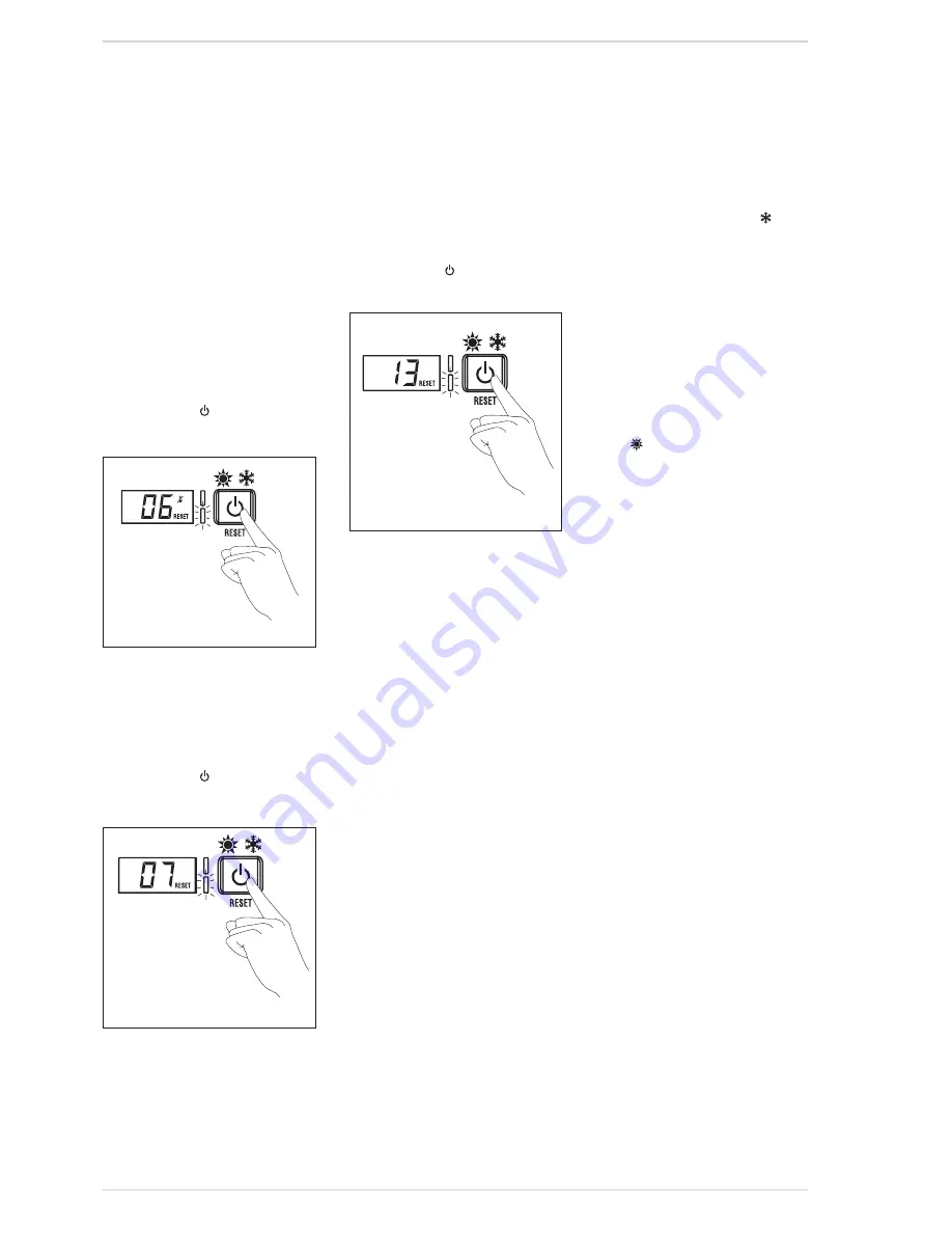
LOCKOUT ALARM 06 (fig. 22/b)
If the flame control has not detected
the presence of the flame after a
complete ignition sequence, or for any
other reason the card cannot “see”
the flame, the boiler will stop and the
display will show the alarm “AL 06”.
Press the key
of the controls to
start up the boiler again.
–
SAFETY THERMOSTAT ERROR
ALARM 07 (fig. 22/c)
Opening of the safety thermostat will
turn off the burner, the display will
show AL07. If the problem persists for
more than one minute, the boiler will
stop and the red LED will turn on.
Press the key
of the controls to
start up the boiler again.
–
FLAME DETECTION ERROR ALARM 08
If a flame is detected when one should
not be present, the boiler will stop and
the display will show “AL 08”
–
D.H.W. SENSOR ERROR ALARM 10
When D.H.W. sensor (SS) is open or
short circuited, the boiler function
in C.H. and DHW and the display will
show alarm “AL 10”. Replace the sensor
because the message disappears.
–
ACTIVATION OF THE EXHAUST
TEMPERATURE SENSOR ERROR “AL
13” (fig. 22/d)
The activation of the exhaust fumes
sensor causes the boiler to stop and
the display will show AL 13.
Press the key
of the controls to
start up the boiler again.
–
EXHAUST TEMPERATURE SENSOR
ERROR “AL 14”
When the exhaust fumes sensor is
opened or short-circuited, the boiler
stops and the displays shows anomaly
AL 14.
–
FAN ERROR “AL 15”
If the fan speed is not within the rated
speed range , the display will show
“AL 15. If the problem persists for more
than two minutes the boiler will stop
for thirty minutes and then attempt to
resume working.
4.7
COMMISSIONING AND
ROUTINE
SERVICE
Commissioning and servicing can only
be done by a qualified engineer.
4.7.1 Commissioning
PLEASE NOTE: The combustion for this
appliance has been checked, adjusted
and preset at the factory for operation
on the gas type defined on the appliance
data plate.
However it is advisable to check
for correct combustion having first
checked:
- That the boiler has been installed in
accordance with these instructions.
- The integrity of the flue system and
the flue seals.
- The integrity of the boiler combustion
circuit and all the relevant seals.
The following procedure should be
done after installation a gas purge and
tightness/drop test have been made.
Ensure that the auto air vent (12 fig. 3) is
opened, turn the electrical supply on.
With the boiler on standby fill the system
and pressurise to 1.5 bar.
Ensure that the pump has been manually
rotated.
Open the gas cock, press the “ mode
key” (fig. 12).
Check the operational (working) gas
inlet pressure.
Set up the boiler to operate at maximum
rate as described in 4.5.1 (Chimney
sweep]).
With the boiler operating in the maximum
rate condition check that the operational
(working) gas pressure at the inlet test
point (see fig 16 item 1) is 21 mb +/- 2
mb.
Ensure that this inlet pressure can be
obtained with all other gas appliances in
the property working.
The boiler will attempt to light.
Press “ mode key” (fig. 12).
The burner will extinguish.
Turn on a DHW tap fully (preferably the
bath tap).
Set the controls to the required values as
shown in the user guide.
Complete the Benchmark sheet enclosed
in this manual.
Explain controls and operation to the
user.
Leave all documentation with the user.
4.7.2 PAR 15 maximum Heating Power
PAR 15 (parameter 15) is set as default
at 81% of the maximum boiler heating
output. This value should be adjusted to
correctly represent the actual heating
requirement for the installation.
4.8
ROUTINE SERVICE
To comply with the conditions of any
extended warranty offered and to
ensure continued safe and efficient
operation, the boiler must be serviced
at regular intervals, at least once a year.
This service must be recorded in the
Benchmark section of this manual.
It is the law that a competent person
such as a Gas Safe Register registered
engineer, must carry out any service
work.
4.8.1 Combustion Check (fig. 23)
Competence to carry out the check of
combustion performance.
PLEASE NOTE: BS 6798: 2009
Specification fro installation and
maintenance of gas-fired boilers of
rated input not exceeding 70 kw net
advises that:
* The person carrying out a combustion
measurement should have been
assessed as competent in the use of a
flue gas analyser and the interpretation
of the results;
* The flue gas analyser should be one
Fig. 22/b
Fig. 22/c
Fig. 22/d
Summary of Contents for COMFORT 30
Page 3: ......
Page 28: ...28 7 EXPLODED VIEWS...
Page 29: ...29...
Page 45: ...NOTES...
Page 46: ...NOTES...
Page 47: ......
Page 48: ...iqe co uk Trade House BA22 8RT Phone 0800 0152252...


