22. Advanced information
The following section is for more advanced users.
GPIO usage / Pin headers)
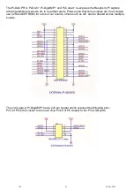
The IQaudIO range of sound cards for the Raspberry Pi take advantage of a number of Pi signals in
order to operate successfully. Some of these signals are solely for the use of the IQaudIO board and
some can be shared with other peripherals, sensors, etc. The information below covers the general
cases. For more Raspberry Pi GPIO information please see the excellent site:
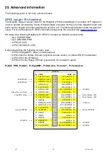
We expect the following Raspberry Pi GPIO to be used by IQaudIO audio boards
• ALL POWER PINS
• ALL GROUND PINS
• GPIO 2/3 (I2C)
• GPIO 18/19/20/21 (I2S)
If appropriate then the following are also used
• GPIO 22 ( mute / unmute support)
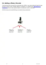
• GPIO 23/24 for Rotary Encoder (physical volume control) or status LED (Pi-CodecZero)
• GPIO 25 for the IR Sensor.
• GPIO 27 for the Rotary Encoder push switch / Pi-CodeZero switch
Pi-DAC PRO, Pi-DAC+, Pi-, Pi-DACZero, Pi-Codec+, Pi-CodecZero
SIGNALS
Pin
#
NAME
NAME Pin
#
1
3.3v
(DC Power)
☐
¤
(DC Power)
5v
2
SHARED USE ------>
3
GPIO2
(I2C SDA1)
¤
¤
(DC Power)
5v
4
SHARED USE ------>
5
GPIO3
(I2C SCL1)
¤
¤
(GROUND)
0v
6
7
GPIO4
(GCLK)
¤
¤
(TXD0)
GPIO14
8
9
0v
(GROUND)
¤
¤
(RXD0)
GPIO15
10
11
GPIO17
(GEN0)
¤
¤
(I2S CLK)
GPIO18
12
<----
-
I2S AUDIO
Rotary Encoder / Button ------>
13
GPIO27
(GEN2)
¤
¤
(GROUND)
0v
14
Pi- (Mute) ------>
15
GPIO22
(GEN3)
¤ ¤
(GEN4)
GPIO23
16
<----
-
Rotary Encoder / LED
17
3.3v
(DC Power)
¤
¤
(GEN5)
GPIO24
18
<----
-
Rotary Encoder / LED
19
GPIO10
(SPI_MOSI)
¤
¤
(GROUND)
0v
20
21
GPIO9
(SPI_MISO)
¤
¤
(GEN6)
GPIO25
22
<----
-
IR Receiver
23
GPIO11
(SPI_CLK)
¤ ¤
(SPI CE0)
GPIO8
24
25
0v
(GROUND)
¤
¤
(SPI CE1)
GPIO7
26
Used by EEPROM ------>
27
ID_SD
(HAT
EEPROM)
¤ ¤
(HAT EEPROM)
ID_SC
28
<----
-
Used by EEPROM
29
GPIO5
¤
¤
(GROUND)
0v
30
31
GPIO6
¤ ¤
GPIO12
32
33
GPIO13
¤
¤
(GROUND)
0v
34
I2S AUDIO ------>
35
GPIO19
(I2S
LRCLK)
¤
¤
GPIO16
36
37
GPIO26
¤
¤
(I2S DIN)
GPIO20
38
<----
-
I2S AUDIO
39
0v
(GROUND)
¤
¤
(I2S DOUT)
GPIO21
40
<----
-
I2S AUDIO
v32
24-Nov-2019
40

