background image

7

/

31

1.3

Microphone Audio Processor Interface Description

1.3.1

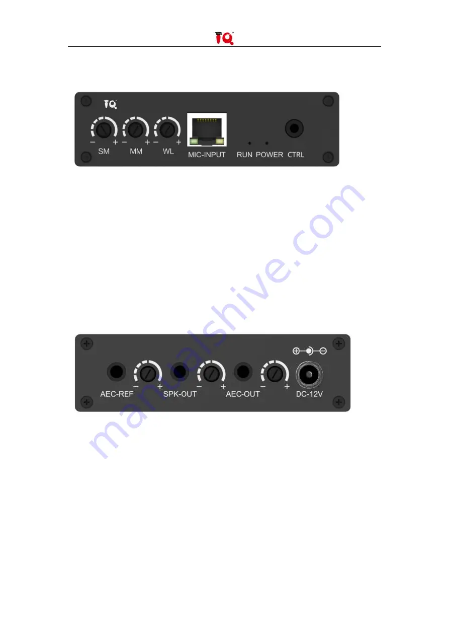
Front Interface

1. SM Input volume adjustment knob of wired vice microphone.

2. MM Input volume adjustment knob of wired main microphone.

3. WL Input volume adjustment knob of wireless main microphone.

4. MIC-INPUT Input interface of network port microphone.

5. RUN Device running indicator, flashing slowly indicates normal operation.

6. POWER Power indicator, keep it on after power on.

7. CTRL Debugging port.

1.3.2

Back Interface

8. AEC-REF Acoustic echo cancellation audio signal input interface, 3.5mm audio interface.

9. AEC-REF Rotate the AEC-REF volume adjustment.

10. SPK-OUT Stereo output to external amplifier or speakers, 3.5mm audio interface.

11. SPK-OUT Rotate the SPK-OUT volume adjustment .

12. AEC-OUT Stereo acoustic echo cancellation processed signal output interface, 3.5mm audio

interface.

13. AEC-OUT Rotate the AEC-OUT volume adjustment knob.

14. DC-12V Power port.

Summary of Contents for IQVideo LCS610

Page 1: ...IQVideo Lecture Capture System LCS610 User Manual ...

Page 2: ...2 31 ...

Page 3: ...aration 8 Chapter 3 Device Connection 8 Chapter 4 Video Station IP Settings 8 Chapter 5 Camera IP Settings 10 5 1 Configuration Software Installation 10 5 2 Network Parameters Setting 11 Chapter 6 Video Station Operation Instructions 12 6 1 Local Recording 12 6 1 1 Network Settings 12 6 1 2 Director Settings 13 6 1 3 Local Recording 14 6 1 4 Video Review and Export 15 6 2 Remote Recording 15 6 2 1...

Page 4: ...e streaming over Internet 17 Chapter 7 Recording System Parameter Settings 17 7 1 Video Station Configuration 17 7 2 External interface 23 7 3 Intelligent Control 24 7 4 User Management 25 7 5 System Management 27 Chapter 8 Abnormal problems and solutions 29 ...

Page 5: ...5 31 Chapter 1 System Components Video Station Auto tracking Camera Teacher Auto tracking Camera Student Ceiling MIC Microphone Audio Processor 1 1 Video Station Interface Description ...

Page 6: ...N Support Access to the Teacher s Computer or Visual Presenter and Other HDMI Video Signals 7 USB Local Recording Video Export 8 AUDIO OUT Audio Recording Output to Audio Processor 9 AUDIO IN Audio Signal Input Such as Microphone 1 2 Teacher Camera Student Camera Interface Description 1 DC 12V Camera Power Interface 2 RS485 Device Control Port 3 RJ45 Gigabit Network Interface POE Supported 4 3 Pin...

Page 7: ...ly indicates normal operation 6 POWER Power indicator keep it on after power on 7 CTRL Debugging port 1 3 2 Back Interface 8 AEC REF Acoustic echo cancellation audio signal input interface 3 5mm audio interface 9 AEC REF Rotate the AEC REF volume adjustment 10 SPK OUT Stereo output to external amplifier or speakers 3 5mm audio interface 11 SPK OUT Rotate the SPK OUT volume adjustment 12 AEC OUT St...

Page 8: ...fault IP 192 168 2 88 and 3 5mm is the student tracking camera student camera default IP 192 168 2 89 The installation height is preferably between 2 2 meters and 2 5 meters Connect all devices and network cables make sure all devices are in the same LAN and ready for setting Chapter 3 Device Connection Chapter 4 Video Station IP Settings Connect the computer to the video station with a network ca...

Page 9: ...ss of the Video Station to 192 168 XXX XXX depending on the local area network re enter the modified IP address on the web page and enter the settings page to add the camera network address rtsp 192 168 XX 88 video1 Teacher Panorama rtsp 192 168 XX 88 video2 Teacher Close up rtsp 192 168 XX 89 video1 Student Panorama rtsp 192 168 XX 89 video2 Student Close up The camera IP address setting ensures ...

Page 10: ...e settings Chapter 5 Camera IP Settings 5 1 Configuration Software Installation Unzip the Camera Configuration Software EDUTrackerClie nt1 4 4 zip to the specified location double click to open the software as shown in the figure below ...

Page 11: ... Setting Click to select the camera in the device list on the left the network parameters and software version information of the current device are displayed on the right and click to modify the IP address to make it consistent with the video station settings After the modification is completed saving the settings without restarting as shown below ...

Page 12: ...ion Operation Instructions 6 1 Local Recording Pic Video station power on state The login interface will be displayed after power on and the system default login password 8888 6 1 1 Network Settings Pic Network setting interface ...

Page 13: ...or page Split screen Before class teachers can choose a suitable split screen mode according to class needs Pic Split screen selection 1 Select the split screen mode you want 2 Enter split screen settings select the camera image to be displayed on each split screen For example in the case of four split screen there are four numbers 1 2 3 4 in the split screen setting corresponding to the four spli...

Page 14: ...elect Switch the recording system will automatically switch the screen at this time the manual split screen cannot be changed Select Tracking the camera automatically tracks the movement of the teacher it is recommended to keep the selected state 6 1 3 Local Recording Click Record to start recording video click Stop to stop recording click Lock to freeze the HDMI input source screen when there is ...

Page 15: ...and the video station are in the same LAN Open the browser and enter the IP address of the video station in the browser default IP http 192 168 1 212 you can view the existing IP on the Video Station Enter the login interface of the Remote Director System as shown in the figure above Enter the username admin Password 8888 same as the password of the local director and then Login to enter 6 2 2 Rem...

Page 16: ...M screen The smart switch button is a toggle switch When the button is turned off the tracking will not be switched and when the button is turned on the camera will switch automatically The Smart Tracking button is a tracking switch When this button is turned off smart tracking is not performed When this button is turned on automatic lens tracking is performed 6 2 3 Watch Videos and Downloads Remo...

Page 17: ...te Director System to start streaming to the live broadcast platform In this time enter the Remote Director System Live when you can view the live preview on the live page it means the streaming is successful Chapter 7 Recording System Parameter Settings 7 1 Video Station Configuration Network Display the network card information and IP information of the current video station support manual setti...

Page 18: ...e of the recorded video and generally do not modify it Pic Local live broadcast and recording parameter settings Local Remote Live Broadcast Parameters If you use public network live broadcast you can freely adjust the code rate according to the school s bandwidth and generally do not modify it ...

Page 19: ...19 31 Pic Remote live broadcast main stream parameter setting Pic Remote live broadcast AUX stream parameter setting Audio Codec Parameters Display the current audio acquisition format ...

Page 20: ...he director channel is not selectable support up to 5 channels to record at the same time File format choose to record files in FLV MP4 format and use MP4 format to record by default Duration limit in the case of long term recording the video will be automatically cut which can be set to 1 2 3 hours Pop up settings after clicking the record button whether to pop up a confirmation dialog box Countd...

Page 21: ...the HDMI output interface corresponding to the recording host interface HDMI out 1 It supports three options director preview and HDMI Pic HDMI output settings Volume Settings Adjust the input and output volume If you need to use the interactive function don t select the Sound in the classroom function ...

Page 22: ...tings OSD Parameter Used to edit the settings of subtitles logo time and title information and select the display position font size and color Pic OSD Parameter settings Opening Ending Mainly used to upload the opening and ending and set the titles of them It is recommended to upload pictures in 1920 1080p jpg format ...

Page 23: ...puter desktop detection sensitivity the smaller the value the more sensitive the recommended value range is 300 Delay protection the minimum hold time when the computer desktop has been switched to the desktop without operation Detection strategy whether to enable computer desktop detection HDMI detection no detection Stop strategy after the computer desktop exceeds the hold time it automatically ...

Page 24: ...screen has been kept on the computer desktop yes no Server Mainly used to connect the video station with other platforms FTP service upload the video to the settings on the FTP server fill in the address IP that needs to be uploaded to the specified server Pic Server parameter settings 7 3 Intelligent Control Scheduled Recording Scheduled recording function support single recording time Pic Schedu...

Page 25: ...ess Control There is a limit that an account cannot have more than two logins at the same time to prevent data loss caused by human misoperation Pic Access control settings 7 4 User Management Role management You can add administrator and user permissions to operate this system ...

Page 26: ...er Management Create a new login user the default password is 8888 Based on the normal operation of the system it supports up to 8 new users Pic Add user Change Password Modify the password of the current login account Pic Change password ...

Page 27: ...keep the power on when the system is upgraded After the upgrade is successful the system will automatically restart Pic Software upgrading Equipment management Device Naming Pic Device naming Mainly display the video station serial number not writable Video station name modifiable used for classroom identification when docking with the platform Device Time ...

Page 28: ... restore the setting fields to the default parameters if necessary please contact the debugging personnel do not operate without authorization Otherwise you should bear the responsibility if data loss caused by your misoperation Pic Data recovery page Screen Lock The lock screen management is used to define the cooling time when the touch screen is automatically locked In the unlocked state if the...

Page 29: ...estart the video station the video station be restarted to take effect b Whether the IP of the camera and the video station are in the same network segment the network segment must be the same c Whether the camera is normally powered on and the network is normally connected 2 There is tracking effect but it cannot be switched automatically a Whether the smart switching and smart tracking are on at...

Page 30: ...30 31 a Whether the networks of both parties are interoperable b After the IP address is set the video stations of both parties must be restarted to take effect ...

Page 31: ...31 31 Kd065EN User Manual 20200119 ...

Reviews: