Security Target
Version 1.1
2022-03-08
42
•
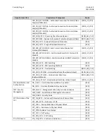
For a Key stuck test failure, the front panel Port LED of that jammed button port will flash.
•
For all other Self-test failures (Firmware integrity, Accessibility of internal memory of the micro-
controller, Computer interfaces isolation functionality, Anti-tampering mechanism) all front panel
LEDs (except for Power LED) flash.
The RPS LEDs flash indicators operate as follows:
•
C
onnecting a “tampered” RPS befor
e KVM power-
up →
The KVM will detect that the RPS is
tampered and reject the connection with RPS
→
The RPS LEDs flash.
•
Connecting a RPS with battery damaged or exhausted to KVM before KVM power-up
→
The KVM
will detect the RPS battery status and reject the connection with RPS
→
The RPS LEDs flash.
•
A connected and aligned RPS will flash all LEDs when it is tampered during normal operation.
A Push button jam self-test failure may be recoverable if the button jam is temporary. Guidance
documentation instructs the user to verify the KVM installation, push buttons, and power cycle the
Secure KVM Switch in order to attempt to recover. This is the only self-test that may be recoverable. If
the button jam is permanent (for example, the push button is broken and truly stuck), the KVM remains
disabled since it fails the button jam self-test.
Users can verify the integrity of the TOE by triggering a self-test (e.g. by powering on or rebooting the
TOE) and examining the front panel LEDs for self-test failures as identified above.
The TOE performs self-tests as described above to demonstrate the correct operation of
active anti‐
tamper functionality (see also 6.5.3 FPT_PHP).
6.6
TOE Access
The TOE display a continuous visual indication of the computer to which the user is currently connected,
and displays the indicator on power up, and on reset.
6.6.1
FTA_CIN_EXT.1
–
Continuous Indications
The TOE displays continuous visual indicators of the computer to which the user is currently connected
at all times when the TOE is powered.
The Port LEDs on the Secure KVM Switch are located on the front panel (of the switch) and the upper-left
side of each push button (of the RPS) provide a continuous visual indication of the selected Port and
corresponding selected computer (bright orange) and the connection status of all other connected
computers (dim orange indicates the connected computer is running). If a RPS is detected and aligned
with KVM, the status of KVM will reflect on both the KVM front panel LEDs and RPS front panel LEDs.
On power up and reset, Port 1 is selected by default.
The TOE supports connected displays from a single source video feed (either single-head or multi-head).
Because of this, the single selected source video feed is always the same channel as all other peripherals,
and indication of the selected channel is indicated through the channel selection LEDs on the TOE chassis.

