background image

Setting Up Your ProEdge-A100

Positioning Your ProEdge-A100

12

Step 2: Understand Your Stand / VESA Mount Kit for ProEdge-A100

The stand for your ProEdge-A100 is dual-purpose: it can be used as a stand or as a VESA mount kit. All screws of 

different types supplied with the stand / VESA mount kit can be stored away inside the main bracket when not needed.

   Screws Stored Away inside the Bracket

The following figure shows different types of screws stored away inside the main bracket.

Screw Type

Number Description

1

2

The largest-size screws used to secure the bracket to a monitor as a VESA mount if the 

middle-size screws cannot firmly secure the bracket and your ProEdge-A100 to the monitor.

2

4

The middle-size screws used to secure the bracket to your ProEdge-A100 and to a monitor 

when using the bracket as a VESA mount.

3

1

The smallest-size screw used to secure the bracket to your ProEdge-A100 as a stand.

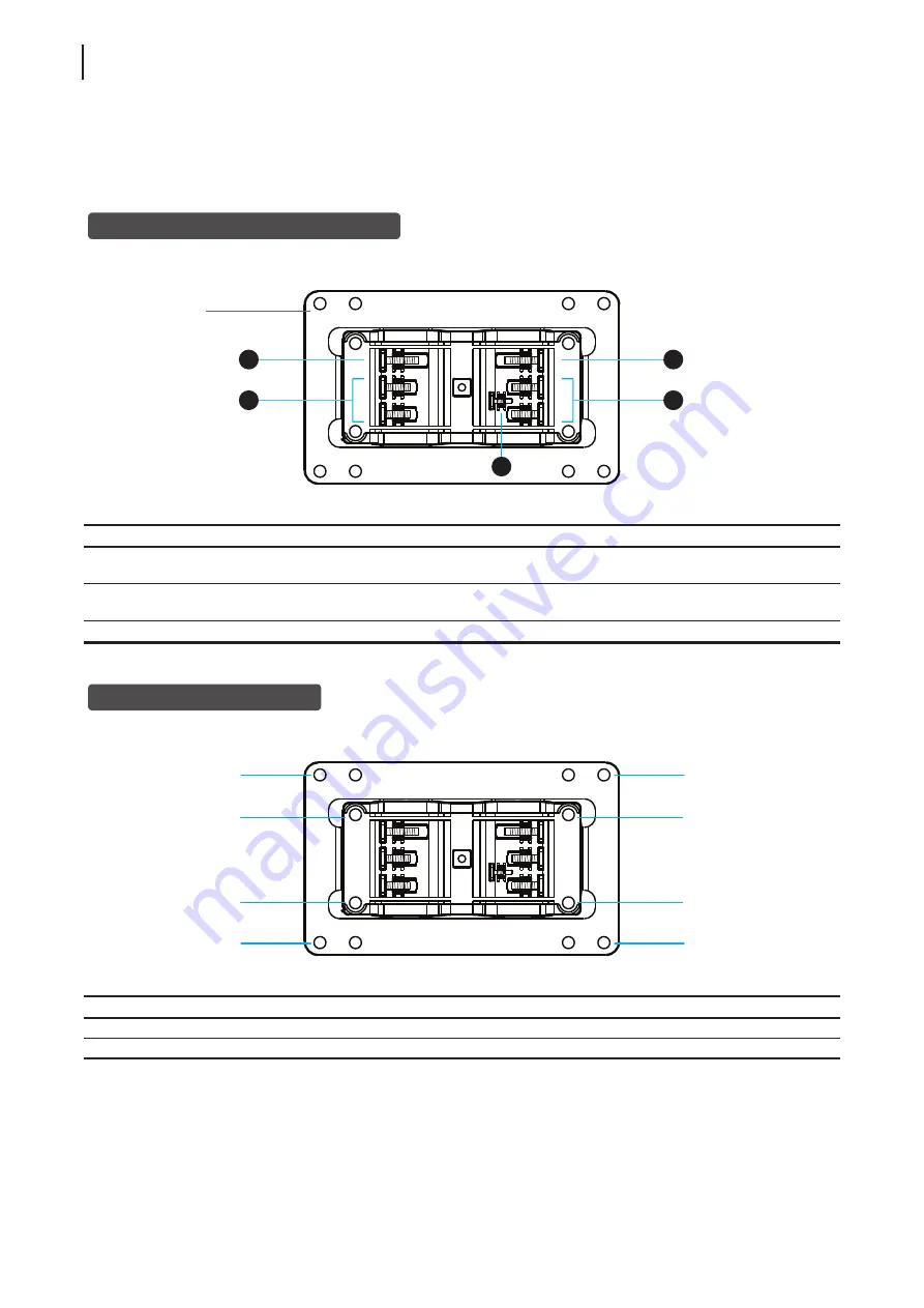
   Mount Holes on the Bracket

Refer to the following figure and descriptions for the VESA mount holes on the bracket.

Mount Hole Description

1

The VESA mount holes used to secure the bracket to a monitor (only two of them will be used).

2

The VESA mount holes used to secure the bracket to your ProEdge-A100 (only two of them will be used).

1

2

1

2

3

Dual-purpose 

bracket

1

2

1

2

1

2

1

2

Summary of Contents for ProEdge-A100 thin client

Page 1: ...ProEdge A100 Thin Client Installation Guide Internal Draft 0 01 2014 I O Corporation ...

Page 2: ...IG ProEdge A100 EN 14053010 ...

Page 3: ...mation contained herein Trademark Statements Microsoft Windows Windows Server RemoteFX and MultiPoint are trademarks or registered trademarks of the Microsoft group of companies Citrix ICA XenApp XenDesktop and VDI in a Box are trademarks of Citrix Systems Inc and or one or more of its subsidiaries and may be registered in the United States Patent and Trademark Office and in other countries VMware...

Page 4: ...ations Provides detailed information on key components of ProEdge A100 thin clients Notes and Warnings Throughout this guide the notes and warnings in the following formats are used to provide important information and prevent injuries to you damage to your devices or loss of data on your system NOTE A note provides important information for a specific situation WARNING A warning provides crucial ...

Page 5: ...g measures Reorient or relocate the receiving antenna Increase the separation between the equipment and receiver Connect the equipment into an outlet on a circuit different from that to which the receiver is connected Consult the dealer or an experienced radio TV technician for help FCC Caution Any changes or modifications not expressly approved by the party responsible for compliance could void t...

Page 6: ... keyboard and mouse that in total require more than 200 mA of rated current during operation WARNING For safety do not make mechanical or electrical modifications to the equipment Do not remove equipment covers and access any of the components inside the equipment Any access inside the equipment without an authorized or certified technician may cause serious injuries and damage For any problem con...

Page 7: ...and reduced power consumption by the factory default settings The display returns to the Display Normal mode upon sensing a request from a user such as moving the mouse or pressing a key To adjust settings for the Display Sleep mode on I O Quick Connection screen click Setup User Interface Screensaver to adjust the settings System Sleep Mode ProEdge A100 doesn t support the System Client Sleep mod...

Page 8: ... vi ...

Page 9: ...d Regulatory Information iii Regulatory Statement iii Regulatory Information iv Safety Information iv Certification Information v 1 Overview 1 1 1 Introduction 3 1 2 Features 3 1 3 Package Contents 3 1 4 Exterior Views 4 1 5 Panel Components 5 1 6 LED Indicators 7 2 Setting Up Your ProEdge A100 9 2 1 Positioning Your ProEdge A100 11 2 2 Assembling the AC Adapter 14 2 3 Getting Connected 15 Specifi...

Page 10: ... viii ...

Page 11: ...and simple endpoint devices 3 1 2 Features Key features of ProEdge A100 3 1 3 Package Contents Check your package contents 3 1 4 Exterior Views Overview of thin client outside elements 4 1 5 Panel Components Descriptions of front and rear panel components 5 1 6 LED Indicators Descriptions of signals for LED indicators 7 ...

Page 12: ......

Page 13: ...and Improved system security More scalability with low cost endpoint devices 1 2 Features The key features of ProEdge A100 thin clients are Support for a wide range of desktop virtualization solutions from industry leading companies Ź Ź Microsoft Remote Desktop Ź Ź Citrix XenApp XenDesktop and VDI in a Box Ź Ź VMware View Support for high definition technologies Ź Ź Microsoft RemoteFX Ź Ź Citrix H...

Page 14: ...Overview Exterior Views 4 1 4 Exterior Views Rear Panel Front Panel Left Front View Right Rear View ...

Page 15: ...n 1 Power LED Indicates the status of power 2 Power button Press to power on the thin client Long press to force power off the thin client 3 Microphone port Connects to a microphone 4 Headphone port Connects to a set of headphones or a speaker system 5 USB port Connects to a USB device 1 2 3 4 5 ...

Page 16: ...display device such as a LCD monitor or a digital projector 8 LAN port Connects to a network 9 USB port Connects to a keyboard or mouse 10 DC IN Connects to an AC adapter NOTE Your ProEdge A100 comes with a DVI I to VGA adapter If only the VGA monitor is available use the supplied DVI I to VGA adapter to connect your VGA monitor to ProEdge A100 s DVI I port For detailed instructions please see sec...

Page 17: ...s on The LAN port of your ProEdge A100 has two LED indicators showing the state of networking The meanings of LED signals are described as follows Left LED transmission rate Right LED transmission activity Meaning LED Signal Off Off The client is not connected to a LAN Off Amber blinking The client connects to a 10 Mbps LAN Orange Amber blinking The client connects to a 100 Mbps LAN Green Amber bl...

Page 18: ...Overview 8 ...

Page 19: ...ve the Stand from Your ProEdge A100 Step 2 Understand Your Stand VESA Mount Kit for ProEdge A100 Step 3 Store Screws inside the Bracket Step 4 Remove Screws from the Bracket Step 5 Mount Your ProEdge A100 11 12 13 13 14 2 2 Assembling the AC Adapter How to assemble the AC adapter and its detached plug 14 2 3 Getting Connected How to connect peripherals and power for ProEdge A100 15 ...

Page 20: ......

Page 21: ...Screws from the Bracket Step 5 Mount Your ProEdge A100 Step 1 Remove the Stand fromYour ProEdge A100 To remove the stand from your ProEdge A100 please do the following 1 Place your ProEdge A100 on a flat surface with the stand side upward 2 Remove the screw that fixes the stand to your ProEdge A100 3 Store away the removed screw inside the stand Detailed instructions will be provided in Step 2 and...

Page 22: ... secure the bracket to a monitor as a VESA mount if the middle size screws cannot firmly secure the bracket and your ProEdge A100 to the monitor 2 4 The middle size screws used to secure the bracket to your ProEdge A100 and to a monitor when using the bracket as a VESA mount 3 1 The smallest size screw used to secure the bracket to your ProEdge A100 as a stand Mount Holes on the Bracket Refer to t...

Page 23: ...screw into the space with your finger until it clicks into place For the smallest size screw use the tip of a screwdriver instead to push the screw NOTE Please refer to the figure and descriptions in Step 2 Understand Your Stand VESA Mount Kit for ProEdge A100 for the correct storage space of each screw Step 4 Remove Screws from the Bracket To remove screws stored inside the bracket please do the ...

Page 24: ... bracket projects out and is closer to the rear panel than the front one as shown below and then secure the bracket to your ProEdge A100 with two 2 screws of type 2 4 Align the mount holes on the bracket with the mount holes on the back of the monitor and then secure the bracket to the monitor with two 2 screws of type 2 or 1 Ensure that your ProEdge A100 is located in the center of the monitor an...

Page 25: ... the supplied DVI I to VGA adapter to connect your ProEdge A100 and monitor Please note that you need to connect and turn on your monitor s before powering up your thin client Otherwise the client may fail to set an appropriate resolution for the monitor s 4 Connect your ProEdge A100 to a power outlet using the AC adapter included in the package NOTE For detailed instructions on how to assemble th...

Page 26: ...Setting Up Your ProEdge A100 16 ...

Page 27: ...x 10 100 1000Mb Ethernet Power Input Output 100 240Vac 0 5A 50 60Hz DC 5Vdc 3A Operating system I O ARM Linux Supported Protocols Microsoft RDP with RemoteFX Citrix ICA with HDX VMware PCoIP Management I O Client Setup I O Device Manager Security 1 x Kensington lock slot Mount Stand VESA mount kit Stand W 68 x H 10 x D 111 mm Dimensions W 39 5 x H 143 x D 103 mm Weight 362 g approx including the d...

Page 28: ... 18 ...

Page 29: ...IG ProEdge A100 EN 14053010 ...

Page 30: ......

Reviews: