Model : PCIe Retimer Card User’s Manual
PAGE 6 OF 7
Connector Locations and Details View
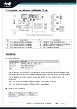
No
Description
No
Description
1 J15 : NMVe0 Oculink Connector
5 J7/J8/J9 :
PCIe Mode Selection
2 J16 : NVMe1 Oculink Connector
6 J3/J4/J5 : SMBus Address Configuration
3 J17 : NVMe2 Oculink Connector
8 J10/J11 : VPP I2C Connector
4 J18 : NVMe3 Oculink Connector
9 JN1 : VPP Bus Selector
Jumpers.
Jumper Setting
:
JN1 is used for VPP0 and VPP1 configuration. Since come of the NVMe controller’s LED
management in VPP/I2C carry 2 slots information while some are carry 4 slots information.
JN1 is designed for users to select what types of VPP protocol will be used in the
application.
JN1: 1-3, 2-4 shunted means VPP0 and VPP1 is separated. (
Default
)
JN1: 3-5, 4-5 shunted means VPP0 and VPP1 is paralleled.
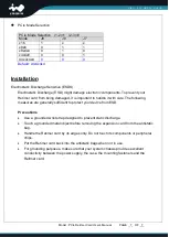
SMBus Address Setting
J5
J4
J3
ADDR_3
ADDR_2
ADDR_1
Default: b’111
Jumper Name Function
J3, J4, J5
SMBus Address Configuration
J7, J8, J9
PCIe Mode Selection
JN1
VPP Bus Selector


