1
3
5
2
4
6
9
8
8
7
7
7
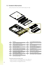
The IW-RS216-07 supports 3.5"/2.5"(15mm) SAS/SATA/NVMe disk bays x 8 pair optional
2.5"(15mm) SAS/SATA/NVMe or 2.5"(7mm) SAS/SATA/NVMe disk bays. Maximum supports U.2
NVMe disk bays x 16. The control panel, USB I/O ports and indicators are located on the handles.
1.3.1 Front Panel Controls and Indicators
No.
Name
Color
Status
Description
1
System Reset Button
N/A
Press the button to activate system reset.
2
NMI Button
N/A
Press the button to activate user-defined function.
3
Power On/Off Button
with LED
Green
Solid on
System is powered on.
N/A
Off
System is off.
4
Chassis ID Button
with LED
Blue
Solid on
Press the button to activate system identification.
5
Hard Disk LED
Amber
Blinking
System HDD accessing.
6
System Fail LED
Amber
Solid on
System Status ( - , + ).
Green
Solid on
System Status ( + , - ).
7
LAN LED (From top to
bottom ranked LAN1-
LAN4)
Green
Blinking
Link between system and network.
N/A
Off
No data transmission or receiving is occurring.
8
USB 3.0 Connector
N/A
USB devices connections.
9
Maximum supports NVMe x 16 disk bays for faster hybrid storage performance.
3.5"/2.5"(15mm) disk bays x 8 pair 2.5"(15mm) disk bays x 4
3.5"/2.5"(15mm) disk bays x 8 pair 2.5"(7mm) disk bays x 8


