


Version 2.00
| Optidrive ODE-3 User Guide |
17
www.invertekdrives.com
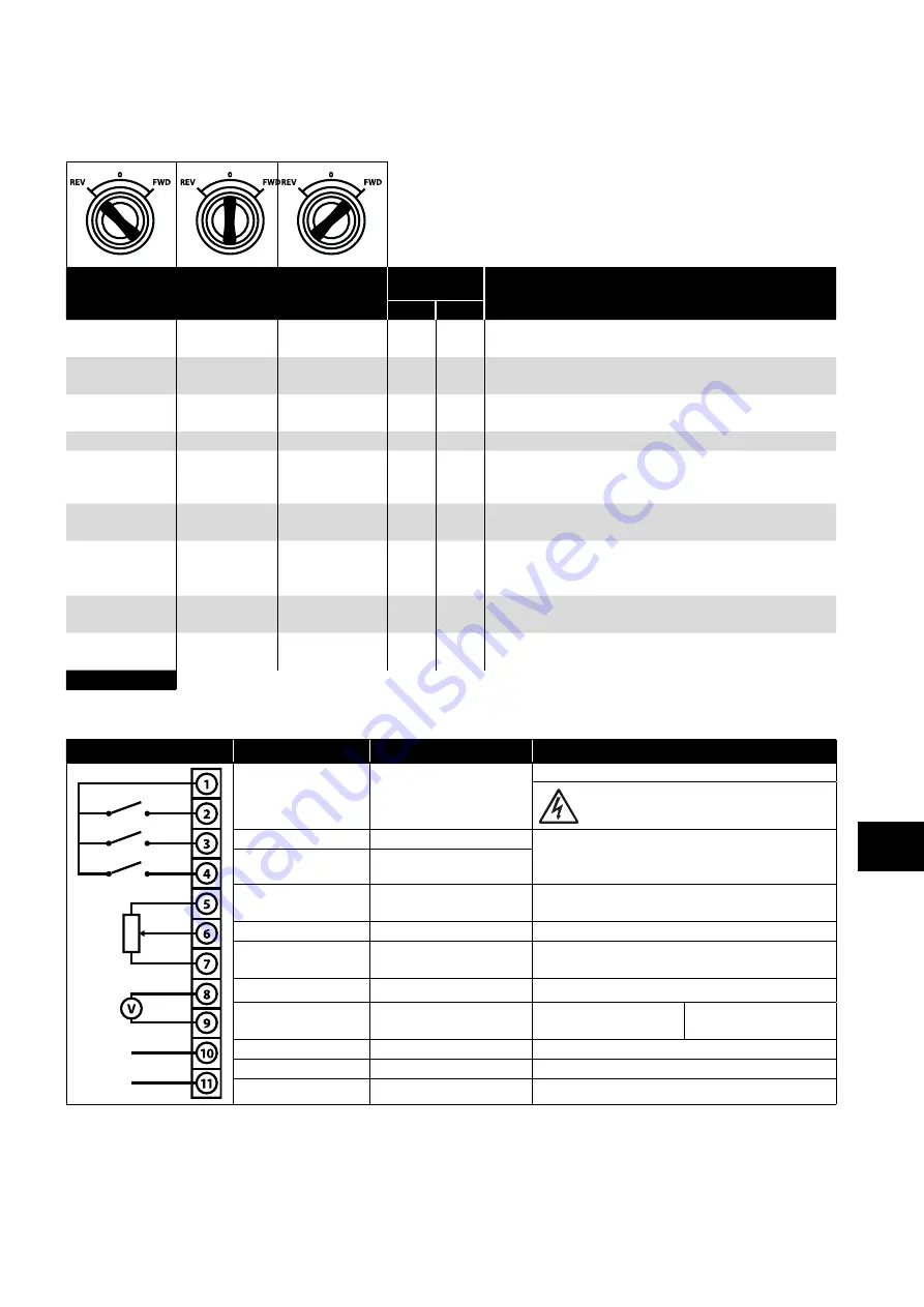
4.7. Using the REV/0/FWD Selector Switch (Switched Version Only)
By adjusting the parameter settings the Optidrive can be configured for multiple applications and not just for Forward or Reverse.
This could typically be for Hand/Off/Auto applications (also known and Local/Remote) for HVAC and pumping industries.
Switch Position
Parameters
to Set
Notes
P-12
P-15
Run Reverse
STOP
Run Forward
0
0
Factory Default Configuration
Run Forward or Reverse with speed controlled from the Local POT
STOP
STOP
Run Forward
0
5,7
Run forward with speed controlled form the local POT
Run Reverse - disabled
Preset Speed 1
STOP
Run Forward
0
1
Run Forward with speed controlled from the Local POT
Preset Speed 1 provides a ‘Jog’ Speed set in P-20
Run Reverse
STOP
Run Forward
0
6, 8
Run Forward or Reverse with speed controlled from the Local POT
Run in Auto
STOP
Run in Hand
0
4
Run in Hand – Speed controlled from the Local POT
Run in Auto 0 Speed controlled using Analog input 2 e.g. from
PLC with 4-20mA signal.
Run in Speed
Control
STOP
Run in PI Control
5
1
In Speed Control the speed is controlled from the Local POT
In PI Control, Local POT controls PI set point
Run in Preset
Speed Control
STOP
Run in PI Control
5
0, 2,
4,5,
8..12
In Preset Speed Control, P-20 sets the Preset Speed
In PI Control, POT can control the PI set point
(P-44=1)
Run in Hand
STOP
Run in Auto
3
6
Hand – speed controlled from the Local POT
Auto – Speed Reference from Modbus
Run in Hand
STOP
Run in Auto
3
3
Hand – Speed reference from Preset Speed 1 (P-20)
Auto – Speed Reference from Modbus
NOTE
To be able to adjust parameter P-15, extended menu access must be set in P-14 (default value is 101)
4.8. Control Terminal Connections
Default Connections
Control Terminal
Signal
Description
1
+24Vdc User Output
+24Vdc user output, 100mA.
Do not connect an external voltage source to
this terminal.
2
Digital Input 1
Positive logic
“Logic 1” input voltage range: 8V … 30V DC
“Logic 0” input voltage range: 0V … 4V DC
3
Digital Input 2
4
Digital Input 3 /Analog
Input 2
Digital: 8 to 30V
Analog: 0 to 10V, 0 to 20mA or 4 to 20mA
5
+10V User Output
+10V, 10mA, 1kΩ minimum
6
Analog Input 1 /
Digital Input 4
Analog: 0 to 10V, 0 to 20mA or 4 to 20mA
Digital: 8 to 30V
7
0V
0 Volt Common, internally connected to terminal 9
8
Analog Output /
Digital Output
Analog: 0 to 10V,
Digital: 0 to 24V
20mA maximum
9
0V
0 Volt Common, internally connected to terminal 7
10
Relay Common
11
Relay NO Contact
Contact 250Vac, 6A / 30Vdc, 5A
Power & Contr
ol Wiring
4


