background image

6   WHEELS

Part No 1171801

55

Invacare® Top End® Everyday Series

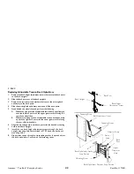
When positioning the other adjustment ring, rotate the ring until the stop is at the bottom of the slot in the camber clamp. The right and left 
stops MUST be positioned opposite to each other or Fine Adjustment on page 56 will not work correctly.
When the left adjustment ring is adjusted to a camber, the right adjustment ring will not touch the camber clamp and when the right 
adjustment ring is adjusted to the other camber the left adjustment ring will not touch the camber clamp.

Stop - Not 

touching 

camber clamp

Adjustment Ring

Camber Clamp

Adjustment Ring

Camber Clamp

Stop - In position for 

one camber, touching 

camber clamp

Stop - In position for 

one camber, touching 

camber clamp

Adjustment Ring

Stop - Not touching 

camber clamp

Adjustment Ring

Summary of Contents for Top End Everyday Series

Page 1: ...of the product BEFORE using this product read this manual and save for future reference Invacare Top End Everyday Series Terminator Terminator Titanium User Manual EN Manuel d utilisation FR Gebruiker...

Page 2: ...Gebruiksaanwijzing pagina 2011 Invacare Corporation All rights reserved Republication duplication or modification in whole or in part is prohibited without prior written permission from Invacare Trad...

Page 3: ...Guidelines 17 Stability Warning 18 Operating Information 19 Weight Capacity 21 Coping with Everyday Obstacles 21 A Note to Wheelchair Assistants 21 Percentage of Weight Distribution 22 Reaching Leanin...

Page 4: ...ase Axles 47 Replacing Quad Release Axles 47 Adjusting Quad Release Handles 48 Removing Play from Rear Wheels 48 Handrim Replacement 49 Repairing Replacing Rear Wheel Tire Tube 50 Opening Closing Camb...

Page 5: ...acing Footrest 69 Installing Adjusting Optional Clamp on Raised Footrest 70 Replacing Adjusting Optional Adjustable Angle One Piece Footplate 70 Adjusting Replacing Anti Tipper 71 Installing Removing...

Page 6: ...acare qualified technician DANGER Danger indicates an imminently hazardous situation which if not avoided will result in death or serious injury WARNING Warning indicates a potentially hazardous situa...

Page 7: ...Invacare s option This warranty does not include any labor or shipping charges incurred in replacement part installation or repair of any such product Invacare s sole obligation and your exclusive rem...

Page 8: ...ice de garantie satisfaisant il doit crire directement Invacare l adresse figurant au bas de cette page Il doit fournir le nom du distributeur l adresse le num ro de mod le du produit sa date d achat...

Page 9: ...3 1 810 7085 ireland invacare com www invacare ie Italia Invacare Mecc San s r l Via dei Pini 62 I 36016 Thiene VI Tel 39 0445 38 00 59 Fax 39 0445 38 00 34 italia invacare com www invacare it Nederla...

Page 10: ...d Everyday Series 10 Part No 1171801 2 Overview 2 1 Label Locations Terminator Terminator Titanium Serial number label located underneath seat The weight capacity label is on the camber tube Refer to...

Page 11: ...or 8 forward FIXED 0 3 6 or 9 REAR FRONT CASTER DISTANCE 17 to 21 Inches 43 18 53 34 cm From outside of back of frame to center of front caster housing FRONT CASTER TO FOOTPLATE DISTANCE 3 5 inches 7...

Page 12: ...n Non Suspension CASTER SIZE 3 4 5 and 6 inch 7 62 10 16 12 7 and 15 24 cm 3 inch 7 62 cm Solid BACK UPHOLSTERY U240 Black Adjustable Tension WEIGHT 20 lbs 9 07 kg SHIPPING WEIGHT 30 lbs 13 6 kg WEIGH...

Page 13: ...2 inches 43 18 53 34 cm From outside of back of frame to center of front caster housing FRONT CASTER TO FOOTPLATE DISTANCE 3 to 5 inches 7 62 12 7 cm FOOT WIDTH 9 to 12 inches 22 86 30 48 cm Average...

Page 14: ...12 7 and 15 24 cm 3 inch 7 62 cm Solid BACK UPHOLSTERY U240 Black Adjustable Tension WEIGHT 17 lbs 7 71 kg SHIPPING WEIGHT 30 lbs 13 6 kg WEIGHT CAPACITY 250 lbs 113 4 kg 400 lbs 181 44 kg with Heavy...

Page 15: ...rating is printed on the side of the tire Conversion formula 1 psi 6 895 kPa approx 7 kPa PSI KILOPASCALS PSI KILOPASCALS 50 345 90 621 55 379 95 655 60 414 100 690 65 448 105 724 70 483 110 758 75 5...

Page 16: ...2 OVERVIEW Invacare Top End Everyday Series 16 Part No 1171801...

Page 17: ...cal personnel before attempting to use this equipment otherwise injury or damage may occur A qualified technician MUST perform the initial set up of this wheelchair also a qualified technician must pe...

Page 18: ...of the five conditions may cause the wheelchair to decrease in stability Use extreme caution when using a new seating position The addition of anti tippers may be required When changes to the left ha...

Page 19: ...tween floors Serious bodily injury may occur Before attempting to transfer in or out of the wheelchair every precaution should be taken to reduce the gap distance Turn both casters parallel to the obj...

Page 20: ...Y CAN OCCUR IN THE EVENT OF A FALL FROM THE PRODUCT Because Top End wheelchairs are made to the specification of the original owner it is unlikely that refurbished product would be suitable to the ano...

Page 21: ...move the handcycle as they may be inadvertently released resulting in possible injury to the user and or assistant When learning assistance techniques for the handcycle have an experienced assistant...

Page 22: ...o maintain stability and balance Lengthening the wheelbase will increase the stability and maintain standard maneuverability of wheelchair Shortening the wheelbase will decrease the stability increase...

Page 23: ...y a continuous motion until the balance point is achieved At this point the assistant will feel a difference in the weight distribution Turn the wheelchair in the desired direction if necessary Slowly...

Page 24: ...ted back to the balance point and in one continuous upward movement the rear wheels should be pulled up and over the curb DO NOT return the front casters to the ground until the wheelchair has been pu...

Page 25: ...om the stairway 5 If equipped turn the anti tippers down Refer to Footrest Anti Tipper on page 53 in this manual WARNING Concerning stairway access Invacare does not recommend that wheelchairs be tran...

Page 26: ...neath you Use a transfer board if at all possible WARNING Before attempting to transfer in or out of the wheelchair every precaution should be taken to reduce the gap distance Turn both casters parall...

Page 27: ...3 SAFETY Part No 1171801 27 Invacare Top End Everyday Series...

Page 28: ...amaged Replace if necessary Ensure hand grips if equipped are not loose Ensure quick release axles and camber inserts are clean Ensure adjustable axle position camber bar is securely tightened Ensure...

Page 29: ...Inspect Adjust Weekly Ensure hand grips if equipped are not loose Ensure quick release axles and camber inserts are clean Ensure quick quad release axles lock properly Inspect handrims for signs of r...

Page 30: ...free of debris Inspect Adjust Periodically Ensure wheelchair rolls straight no excessive drag pull to one side Ensure wheel locks are easy to engage Inspect seat and back upholstery for rips or saggin...

Page 31: ...on lubricant Veers Right Veers Left Sluggish Turn or Performance Casters Flutter Squeaks and Rattles Looseness in Chair Solutions X X X X Check tires for correct and equal pressure X X X X Check for l...

Page 32: ...red to the rear wheels Refer to 8 Periodically adjust wheel locks as tires wear Refer to 9 Periodically check caster wheel bearings to make sure they are clean and free from moisture Use a Teflon lubr...

Page 33: ...4 SAFETY INSPECTION TROUBLESHOOTING Part No 1171801 33 Invacare Top End Everyday Series...

Page 34: ...he user s condition are directly related to the wheelchairs stability Any change to one or any combination of the five may cause the wheelchair to decrease in stability Use extreme caution when using...

Page 35: ...is measured relative to true vertical with the chair sitting on a level surface The plus sign increases the back angle and the minus sign decreases the back angle The resulting back angle will vary s...

Page 36: ...ghten the placement screw so that the screw and jam nut are snug against the bottom of the back cane Detail B 4 Remove the mounting screw that secures the adjustment square to the back angle plate Det...

Page 37: ...ten securely 8 Repeat STEPS 2 6 for remaining back cane 9 Unfold the back until the plunger pins lock into the mounting holes in the adjustment square 10 Unthread the mounting screw until head of scre...

Page 38: ...L 8 4 0 Back Cane 75 Seat Rail Adjustment square to be positioned at 8 Back Angle Plate Seat Rail Back Cane 79 Adjustment square to be positioned at 4 Back Angle Plate 83 Back Cane Seat Rail Adjustmen...

Page 39: ...veryday Series DESIRED SEAT ANGLE ADJUSTMENT SQUARE POSITION NUMERICAL GRAPHICAL 4 8 87 Back Cane Seat Rail Adjustment square to be positioned at 4 Back Angle Plate 91 Seat Rail Back Cane Adjustment s...

Page 40: ...the wheelchair Installing 1 Install the new back upholstery onto the back posts 2 Wrap the end of a fastening flap around the back post 3 Insert the end of the fastening flap through the loop 4 Wrap...

Page 41: ...econd is to keep the cushion from sliding out of the back of the wheelchair The third is a sacral support depending upon how far or tight the flap is pulled under the seat cushion WARNING The position...

Page 42: ...ar of the wheelchair B Slide adjuster strap section of adjustable tension back upholstery up onto the right back post with the upper grommet hole facing the rear of the wheelchair 6 Align the mounting...

Page 43: ...back upholstery to the back posts and remove from the back posts 2 Press the push pin on the back post insert tube in and adjust the back height to one of four heights depending on original back heigh...

Page 44: ...33 02 cm 15 38 1 cm 17 43 18 cm 3 11 27 94 cm 12 30 48 cm 14 35 56 cm 16 40 64 cm 18 45 72 cm 4 N A 13 33 02 cm 15 38 10cm 17 43 18 cm 19 48 25 cm 5 N A 14 35 56 cm 16 40 64 cm 18 45 72 cm 20 50 8 cm...

Page 45: ...5 BACK Part No 1171801 45 Invacare Top End Everyday Series...

Page 46: ...th motion refer to WARNING After any adjustments repair or service and before use make sure all attaching hardware is tightened securely Otherwise injury or damage may occur CAUTION Changing the size...

Page 47: ...xisting quick release axle from rear wheel 3 Insert new quad release axle through rear wheel hub 4 Slide locking collar onto quad release axle until it is snug against rear wheel and tighten securely...

Page 48: ...unterclockwise 4 Tighten the locking screw 5 Install the rear wheel and quad release axle onto the wheelchair Refer to 6 Flip the handle of the quad release axle down to release the detent pin ensurin...

Page 49: ...Install new handrim by reversing STEPS 2 4 6 Inflate the tire to the recommended psi WARNING The tire must be fully deflated before any disassembly procedures can be performed otherwise injury or dam...

Page 50: ...asters on page 65 ONLY after contacting Invacare Anti tipper height if applicable must also be adjusted to maintain 1 1 2 to 2 inch 3 81 to 5 08 cm clearance between bottom of the anti tipper wheels a...

Page 51: ...ick Release Levers Secure the quick release lever to the camber clamp by threading it completely into the camber clamp Push the quick release lever on the camber clamps to the closed position Standard...

Page 52: ...clamp 8 Close the camber clamp Refer to 9 Repeat STEPS 1 8 for opposite side of wheelchair 10 Install rear wheel to the wheelchair Refer to 11 Adjust toe in toe out of wheelchair Refer to Perform this...

Page 53: ...of two conditions exists If the back centerline measurement of the rear wheels is SMALLER than the front centerline measurement of the rear wheels a TOE OUT condition exists If the back centerline mea...

Page 54: ...e between the center lines at the rear and front of the rear wheels at approximately 12 inches 30 48 cm from the ground floor 6 Repeat STEPS 1 4 until the toe in toe out measurement is less than 1 2 i...

Page 55: ...ctly When the left adjustment ring is adjusted to a camber the right adjustment ring will not touch the camber clamp and when the right adjustment ring is adjusted to the other camber the left adjustm...

Page 56: ...lity increase the maneuverability and distribute additional weight onto the rear wheels This adjustment is required anytime the camber insert is repositioned Rear wheels are removed from the drawings...

Page 57: ...xcessive drag to either side Securely tightening one hex screw at a time ensures that the camber clamps will sit flush on the wheelchair frame The distance between the back post and the back of the to...

Page 58: ...osite axle nut and axle bolt Perform this procedure on one side of the wheelchair at a time for ease of adjustment The wheelbase width can be increased decreased by 1 inch 2 54 cm The number of thread...

Page 59: ...er clamps 3 Remove the two rear wheels 4 Adjustable Camber System Only Remove the camber inserts positioned in the axle tube WARNING NEVER position the camber inserts in the axle tube with more than 3...

Page 60: ...noted in STEP 1 Make sure there are no more than 3 inches 12 indexing marks of the camber inserts outside of the axle tube 13 Adjustable Camber System Only Slide the indexing ring on the camber insert...

Page 61: ...lot in Axle Tube Notch in Axle Tube Camber Clamp Axle Tube Adjustable Camber System Front of Wheelchair Camber Tube With Single Camber Rear of Wheelchair Front of Wheelchair The performance of the whe...

Page 62: ...the quick release levers are in the closed position before using the wheelchair otherwise injury or damage to the wheelchair may occur STANDARD and suspension camber clamps Make sure the hex screws ar...

Page 63: ...step 9 Toe In Toe Out Measurement is Not Within 1 8 inch 32 cm Repeat steps 1 7 until toe in toe out measurement is within 1 8 inch 9 Open the right camber clamp 10 Reposition the camber inserts to th...

Page 64: ...ill Rotate Down only Ground Floor 90 Angle Place L Square Here Flat Edge of Camber Tube Lower Degree of Camber Right Tab Stopped Against Upper Edge of Camber Clamp Right Toe Adjustment Ring Left Tab S...

Page 65: ...up the front caster and two spacers with the mounting hole in the fork determined in STEP B i iii Reinstall the mounting screw threaded sleeve assembly through the fork front caster and two spacers 4...

Page 66: ...the wheelchair frame iv Repeat this procedure for the opposite wheel lock v Engage the wheel locks and push against the wheelchair to determine if the wheel locks engage the rear wheels enough to hol...

Page 67: ...straps 7 Securely latch the four remaining adjuster straps together 8 Reinstall the seat cushion and back upholstery WARNING After any adjustments repair or service and before use make sure all attac...

Page 68: ...7 SEAT Invacare Top End Everyday Series 68 Part No 1171801...

Page 69: ...d to the wheelchairs stability Any change to one or any combination of the five may cause the wheelchair to decrease in stability Use extreme caution when using a new seating position The addition of...

Page 70: ...Replacing the Footrest 1 Loosen but DO NOT remove the two allen screws that secure the footrest to the wheelchair frame 2 Slide the existing footrest tubes out of the wheelchair frame and install new...

Page 71: ...d before use make sure all attaching hardware is tightened securely Otherwise injury or damage may occur Anti tippers MUST be attached at all times Inasmuch as the anti tippers are an option on this w...

Page 72: ...ase button engages 3 Press in the release button on the anti tipper bar and install the anti tipper wheels onto the new anti tipper bar 4 Repeat STEPS 1 3 for the opposite anti tipper 5 Measure the di...

Page 73: ...p receivers Position swivel anti tip so it is even with wheels on chair or extends beyond them Tighten set screws Removing 1 Loosen set screws on anti tip receivers 2 Slide the swivel anti tip out of...

Page 74: ...8 FOOTREST ANTI TIPPER Invacare Top End Everyday Series 74 Part No 1171801 Anti Tippers Anti Tipper Set Screw Anti Tipper Receiver Detail view from rear of wheelchair...

Page 75: ...t and the suspension base 7 Insert the pivot pin into the mounting hole 8 Install the outer allen screw into the pivot pin 9 Use an allen wrench to hold the outer allen screw in position 10 While hold...

Page 76: ...unting screw assembly DO NOT use excessive force 7 Apply Loctite 242 to the mounting screw 8 Reinstall the mounting screw into the threaded sleeve and tighten securely CAUTION DO NOT use excessive for...

Page 77: ...9 SUSPENSION Part No 1171801 77 Invacare Top End Everyday Series...

Page 78: ...Representative Invacare International Sarl Route de Cit Ouest 2 1196 Gland Switzerland Tel 41 22 354 60 10 Fax 41 22 354 60 11 Manufactured by Top End Sports and Recreation Products 4501 63rd Circle...

Reviews: