INTORQ BFK458 Translation Of The Original Operating Instructions Download Page 29

Mechanical installation

Kendrion INTORQ | BA 14.0225 | 05/2022

29

NOTICE

If you are using the spring-applied brake for reverse operations, glue the hub to the shaft.

NOTICE

When using the spring-applied brake as a safety brake: Observe the information concern-
ing the shaft-hub connection in section Applications with special safety requirements
("Safety Brake"), Page 10.

5.5

Mounting the brake

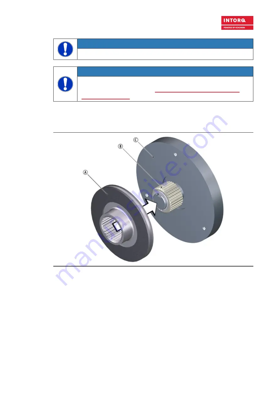
Mounting the rotor (without friction plate / without brake flange)

Fig. 12: 

Assembly of the rotor

A

Rotor

B

Hub

C

End shield

1. Push the rotor on the hub.

2. Check if the rotor can be moved manually.

Summary of Contents for BFK458

Page 1: ...INTORQ BFK458 for NORD Drivesystems Spring applied brake with electromagnetic release Translation of the Original Operating Instructions www kendrion com...

Page 2: ...of printing Claims referring to drive systems which have already been supplied cannot be derived from this infor mation illustrations and descriptions We do not accept any liability for damage and ope...

Page 3: ...TORQ Not coded Connection voltage hub bore diameter options Checking the delivery After receipt of the delivery check immediately whether the items delivered match the accompanying pa pers Kendrion IN...

Page 4: ...rements Safety Brake 10 3 2 Design 12 3 2 1 Basic module E 12 3 2 2 Basic module N 13 3 3 Function 13 3 4 Braking and release 14 3 5 Project planning notes 14 3 6 Brake torque reduction 14 3 7 Optiona...

Page 5: ...cable 40 7 Commissioning and operation 41 7 1 Possible applications of the Kendrion INTORQ spring applied brake 41 7 2 Function checks before initial commissioning 42 7 2 1 Function check of the brak...

Page 6: ...numbers Decimal separator Point The decimal point is always used For ex ample 1234 56 Page reference Underlined red _____ Reference to another page with additional information For example Using these...

Page 7: ...ged 1 4 Terminology used Term In the following text used for Spring applied brake Spring applied brake with electromagnetic release Drive system Drive systems with spring applied brakes and other driv...

Page 8: ...ting frequency thermal parameter of the brake Shmax 1 h Maximum permissible operating frequency depending on the friction energy per switching operation sL mm Air gap the lift of the armature plate wh...

Page 9: ...operation Take appropriate safety measures to ensure contact touch protection Follow all specifications and information found in the Operating Instructions and the corresponding documentation These m...

Page 10: ...m com ply with the standard braking torque in order to meet the high safety requirements Please note the following conditions Proper and intended usage of the brake as described in Standard applicatio...

Page 11: ...ensuring that there is a secure connection between the shaft and the hub Follow the information in the chapter Installing the hub onto the shaft Page 28 to ensure a safe shaft to hub connection Observ...

Page 12: ...adjustable the braking torque can be reduced using the torque adjustment ring 3 2 1 Basic module E Fig 1 Design of a INTORQ BFK458 spring applied brake Basic module E complete stator rotor hub flange...

Page 13: ...with friction linings In its de energized state the rotor is clamped with braking force applied by pressure springs between the armature plate and a counter friction surface This corre sponds to a fa...

Page 14: ...hin the technical specifications of the brake Since the material properties of the friction linings are subject to fluctuations and as a result of different environmental conditions deviations from th...

Page 15: ...emperature 20 C to 40 C Standard Notice The Kendrion INTORQ BFK458 size 06 to 10 spring applied brakes described in these operat ing instructions may be used in normal operation in areas where there i...

Page 16: ...or operating brakes and holding brakes with emergency stop For basic module E the brake torque can be reduced using the torque adjustment ring in the stator The ad justment ring may only be unscrewed...

Page 17: ...peed and permissible limiting speeds Size sLN 0 1 0 05 sLmax Max adjustment per missible wear distance Rotor thickness Protrusion adjustment ring min 1 max hEmax mm mm mm mm mm mm 06 0 2 0 5 1 5 4 5 6...

Page 18: ...hout adjusting ring without counter friction surface Size b dJ7 1 spec dH7 2 standard d1 d2 d3H8 d5 d6j7 d7 06 88 10 10 11 12 14 15 3xM4 72 25 91 87 08 106 5 11 12 14 15 20 3xM5 90 32 109 105 10 132 3...

Page 19: ...7 16 3 116 63 10 48 4 2 9 27 4 132 73 3 Size h7 h8 h9 h11 I I1 sLN 06 23 32 8 56 1 5 18 400 0 2 4xM4 37 7 08 41 3 65 20 4xM5 49 10 42 4 77 8 4xM6 54 Tab 8 Technical specifications Size Mass of stator...

Page 20: ...ion voltage 4 4 Switching times The operating times listed here are guide values which apply to DC switching with rated air gap sLN warm coil and standard characteristic torque The given operating tim...

Page 21: ...ve rectifiers and coils with a con nection voltage of 205 V DC at sLN and 0 7 IN For rectifiers from the manufacturer Nord Drive Systems the same operating times can be applied Engagement time The tra...

Page 22: ...e switching The specified disengagement times always refer to control using Kendrion INTORQ rectifiers and rated voltage 4 5 Friction work operating frequency Friction work Q J R Operating frequency S...

Page 23: ...it may become necessary to connect a spark suppressor in parallel with the AC voltage Spark suppressors are available on request depending on the coil voltage 4 7 Emissions Heat Since the brake conve...

Page 24: ...delivery Verify the dimension sHL after the installation Brake completely installed Stator not attached to the motor Fig 7 Positions of the adjustment dimensions that must be checked Size SLN 0 1 0 05...

Page 25: ...CE mark Fig 9 Name plate example Kendrion INTORQ Manufacturer ta 40 C Permissible ambient temperature Class F Insulation class F BFK458 06N Type refer to Product key Page 3 24 V DC Rated voltage 20 W...

Page 26: ...th Kendrion IN TORQ before using other materials written confirmation is required for such usage If a friction plate is used as a counter friction surface the customer must ensure that it is fully sup...

Page 27: ...s Diameter Nm mm mm mm mm 06 1 to 12 3 8 7 5 5 45 55 08 4 9 10 7 52 55 10 5 12 68 75 NOTICE Tightening torques refer to the table Rated data Screw set for brake mounted on motor friction plate Page 17...

Page 28: ...le by using a circlip Note the following when mounting the hub on the brake The supporting length of the key should be equal to the hub length chosen The hub side dimensioning of the key connection ta...

Page 29: ...ng applied brake as a safety brake Observe the information concern ing the shaft hub connection in section Applications with special safety requirements Safety Brake Page 10 5 5 Mounting the brake Mou...

Page 30: ...Terminal clip D Rotor E End shield 3 Screw the complete stator to the end shield Use the supplied screw set and a torque wrench for tight ening torque refer to the table Rated data Screw set for brake...

Page 31: ...cs for air gap specifications Page 17 Fig 15 Adjusting the air gap 6 If the measured value sL is outside of the tolerance sLN readjust this dimension Loosen the socket head cap screws slightly and adj...

Page 32: ...lling the friction plate optional Fig 16 Mounting the friction plate A Stator B Rotor C Friction plate D End shield 1 Place the friction plate against the end shield The lip edging of the friction pla...

Page 33: ...or D Armature plate E Sleeve bolt F Friction plate G End shield NOTICE The cover ring may only be used in conjunction with a friction plate 1 Pull the cables through the cover ring 2 Slide the cover r...

Page 34: ...the armature plate and through the bore hole in the stator 4 Screw the hex head screws into the yoke pins 5 Tighten the hex head screws to fasten the armature plate against the stator 6 Remove the te...

Page 35: ...ly be made by trained electricians Make sure that you switch off the electricity before working on the connections There is a risk of unintended start ups or electric shock NOTICE Make sure that the s...

Page 36: ...ig 19 Supply Phase neutral Bridge rectifiers Half wave rectifiers BEG 1xx UN V DC 0 9 UV V AC BEG 2xx UN V DC 0 45 UV V AC 3 3 U2 W2 V2 UN L1 L2 L3 UV V1 U1 W1 UV BN BK BU 4 2 1 4 pole BEG 14x BEG 24x...

Page 37: ...upply Phase neutral Bridge rectifiers Half wave rectifiers BEG 1xx UN V DC 0 9 UV V AC BEG 2xx UN V DC 0 45 UV V AC 3 3 U2 W2 V2 UN L1 L2 L3 UV V1 U1 W1 UV BN BK BU 4 2 1 6 pole BEG 16x BEG 26x Fig 22...

Page 38: ...23 Supply Phase N Bridge rectifiers Half wave rectifiers BEG 1xx UN V DC 0 9 UV V AC BEG 2xx UN V DC 0 45 UV V AC L1 L2 UV UN BN BK BU 4 2 1 4 pole BEG 14x BEG 24x 6 pole BEG 16x BEG 26x Fig 24 Supply...

Page 39: ...45 UV V AC 1 For most regional national high voltage mains voltages this only makes sense for supplies on L1 and N L1 N L1 L2 UV UN BN BK BU 4 2 1 4 pole BEG 14x BEG 24x 14 198 00 xx or Fig 26 Supply...

Page 40: ...ndrion INTORQ BA 14 0225 05 2022 40 6 6 Minimum bending radius for the brake connection cable Size Wire cross section Minimum bending radius 06 AWG 20 27 5 mm 08 10 Tab 14 Minimum bending radius for t...

Page 41: ...ply to IP54 protection Because of the many ways the brake can be used it is necessary to check the functionality of all me chanical components under the corresponding operating conditions Notice Funct...

Page 42: ...the two bridges on the motor terminals Do not disconnect the supply connections to the brake If the rectifier for the brake supply is connected to the neutral point of the motor also connect the neut...

Page 43: ...15 Actuating forces 1 Make sure that the motor and brake are de energized 2 Pull with some force on the lever until the force increases sharply The rotor must now rotate freely A small residual torqu...

Page 44: ...orm a test braking procedure if necessary reduce the braking torque depending on your specifi cations and requirements 7 4 Operation DANGER Danger rotating parts The running rotor must not be touched...

Page 45: ...s reduces the braking torque Note the correct position of the tappet notches on the torque adjustment ring Only the latched in positions are permitted It is forbidden to operate the brake when the not...

Page 46: ...Effect Influencing factors Rotor Service braking Wear of the friction lining Friction work Emergency stops Overlapping wear during start and stop of drive Active braking via the drive motor with suppo...

Page 47: ...The rotor hub connection the springs the armature plate and the sleeves are particu larly subject to operational wear If there is a requirement for a longer service life service life optimized soluti...

Page 48: ...Refer to Checking the rotor thick ness Page 50 Check the play of the rotor gear teeth replace worn out rotors Refer to Replacing the ro tor Page 50 Check for breaking out of the torque support at the...

Page 49: ...plate 8 3 4 Adjusting the air gap DANGER Danger rotating parts The brake must be free of residual torque NOTICE Please observe when mounting the flange design with additional screws Clearing holes for...

Page 50: ...the screws evenly and then remove them 3 Pay attention to the connection cable during this step Remove the complete stator from the end shield 4 Pull the rotor off the hub 5 Check the hub s gear teet...

Page 51: ...Hand release with standard lever Mounting kit B Cap Basic module N C Screw set DIN EN ISO 4762 8 8 in various designs and lengths for mounting to the motor friction plate D Complete stator module E Co...

Page 52: ...nal resistance Refer to Rated data for coil power Page 19 for the values If re sistance is too low replace the complete stator Check the coil for short to ground using a multimeter If there is a short...

Page 53: ...e retrofitting Page 34 Air gap sL too small Check the air gap sL and adjust if necessary Adjusting the air gap Page 49 Rotor is too thin Rotor has not been replaced in time Replace the rotor Replacing...

Page 54: ...les F INTORQ Shanghai Co Ltd 600 6 B No 600 Xin Yuan Nan Road Building No 6 Zone B Nicheng town Pudong 201306 Shanghai 86 21 20363 810 86 21 20363 805 info cn intorq com F INTORQ US Inc USA 300 Lake R...

Reviews: