background image

(329PO)  MODEL ECO5110&6110  SALTWATER SYSTEM  ENGLISH  7.5” X 10.3”  PANTONE 295U  01/22/2021

329

PO


SAVE THESE INSTRUCTIONS

English

Page 18

OPERATION INSTRUCTIONS (continued)

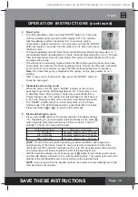
6

Boost cycle

• 

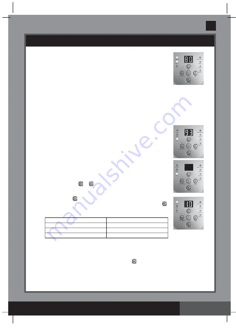
First time installation, press and hold “BOOST” button for 5 seconds 
until the indicator lights up and the LED display “80”. This indicates  
that the saltwater system has started E.C.O. and more sodium 
hypochlorite sanitizer production. You can press and hold the “BOOST” 
button for another 5 seconds until the indicator is off, which will cancel 
the Boost cycle. 

• 

The boost operating hours is 8 times the amount of time programmed into the system, i.e. if 
your saltwater system operating time is 2 hours, the boost procedure will run 8 x 2 = 16 hours. 
After boost procedure has been completed, the system will automatically switch to the 
normal working mode.

• 

Once the boost is operating, check whether the filter pump operating hours have been 
set properly. For example, the boost operating time is 8 hours, the filter pump should be 
set to run for 8 hours at least. Increase the filter pump operating time if necessary. 


Note: 

If an Intex filter pump is attached to the system, set the pump switch to on “I” 

position.

• 

After a heavy rain or if the pool is dirty, press the “BOOST” button to 
shock the pool again.

7

Stand-by/power saving mode:

• 

When the cycle ends, the green “SLEEP” indicator on the control  
panel lights up and the LED display flashes “93”. The system is now  
in Stand-By mode. After a while, it shuts down and sets itself in a  
Power Saving mode. The system will automatically turn itself back on 
in 24 hours, starting its daily cycle of sodium hypochlorite production.

• 

The “SLEEP” indicator stays on, while the system is in the Power 
Saving mode. The LED display however, goes blank after 5 minutes. 
Press any button ( 

 or 

 ) to view the last LED code.

8

Electrode Self-Clean cycle:

• 

Press and hold 

 button for 5 seconds until the LED display flashes  

“10”. Depending on your pool water calcium hardness level, press 


button again to select the self-clean cycle time as below. Total of 3 
settings: 14 hours, 10 hours and 06 hours.


NOTE:

 The life of the cell varies depending on water conditions, pool usage and 

operating time of the device. Select 14 hours cycle time to maximize the life of the 
electrolytic cell if the calcium hardness level is up to 150 ppm. Manual routine cleaning 
and maintenance will further lengthen the life of the electrolytic cell.

• 

With the desired self-clean hours showing, press 

 button to lock the keypad controls 

and the LED display will return to the normal operating time. The system will reverse the 
polarity of the electrode 

(5)

 every time according to the selected hours.


NOTE: 

If you forget to lock the keypad controls, the system will automatically lock it and 

start working 5 seconds later.

Calcium Hardness

Self-clean cycle time 

0 - 150 ppm

Reverse polarity every 14 hours

150 - 250 ppm

Reverse polarity every 10 hours

250 - 350 ppm

Reverse polarity every 06 hours

Summary of Contents for ECO5110

Page 1: ...ome Toys Airbeds and Boats available at fine retailers or visit our website listed below Due to a policy of continuous product improvement Intex reserves the right to change specifications and appeara...

Page 2: ...Salt Table 12 Intex Pools Cyanuric Acid Table 13 Intex Pools Operating Time Table 14 15 Non Intex Pools Salt Table 16 Non Intex Pools Cyanuric Acid Table 16 Non Intex Pools Operating Time Table 16 Ope...

Page 3: ...e risk of electric shock do not use extension cords timers plug adaptors or converter plugs to connect unit to electric supply provide a properly located outlet Do not attempt to plug in or unplug thi...

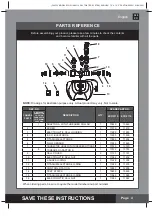
Page 4: ...CTION TO FILTER PUMPS WITH 1 1 4 32MM HOSE SIZE ECO5110 ECO6110 1 ADAPTOR A WITH THREADED COLLAR 1 10849 10849 2 SCREW 2 11519 11519 3 ELECTROLYTIC CELL HOUSING 1 11898 11903 4 E C O ELECTRODE 1 11900...

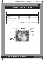
Page 5: ...Pool E C O Electrodes Model ECO5110 ECO6110 Power 110 120 Volt AC 110 120 Volt AC Amperage 0 6 A 1 1 A Wattage 65 W 125 W Ideal Salt Level 3000 ppm parts per million 3000 ppm parts per million E C O C...

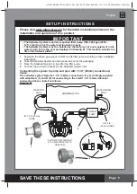
Page 6: ...connections It is accordingly supplied with adaptors A 1 and B 8 for connecting to the small 1 1 4 32mm diameter connections hoses Install as follows Drawing 1 IMPORTANT The Saltwater System requires...

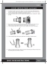
Page 7: ...water pool system 2 Connect the adaptor A 1 to the electrolytic cell 3 outlet as shown in Drawing 1 Tighten securely 3 Disconnect the water return hose from the filter pump connection and connect it t...

Page 8: ...irectly to step 2 if your pool is empty If your above ground pool is filled with water close the plunger valves before installing the Saltwater System 2 Disconnect the water return hose from the filte...

Page 9: ...the connection Connection to 1 1 4 32mm hose 1 Connect one end of adaptor B 8 to the connector hose 7 Tighten securely 2 Now connect the other end of adaptor B 8 to the filter pump outlet Tighten sec...

Page 10: ...to the electrolytic cell 3 outlet Tighten securely 2 The adapter A 1 is now fitted to the Saltwater System The following step is to connect the water return hose to the adaptor A 1 with a hose clamp C...

Page 11: ...eeded The salt in the pool is constantly recycled Adding Salt 1 Switch the filter pump on to start the water circulation 2 Keep the Saltwater System turned off 3 Determine the amount of salt to be add...

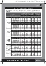
Page 12: ...49cm x 132cm 20 x 48 610cm x 122cm 22 x 52 671cm x 132cm 24 x 52 732cm x 132cm 26 x 52 792cm x 132cm 15 8 x 49 478cm x 124cm 16 8 x 49 508cm x 124cm 18 8 x 53 569cm x 135cm 18 x 10 x 42 549cm x 305cm...

Page 13: ...2 610cm x 305cm x 132cm 24 x 12 x 52 732cm x 366cm x 132cm 32 x 16 x 52 975cm x 488cm x 132cm 2587 9792 0 6 0 3 2822 10681 0 7 0 3 3284 12430 0 8 0 4 3736 14141 0 9 0 4 3754 14209 0 9 0 4 4273 16173 1...

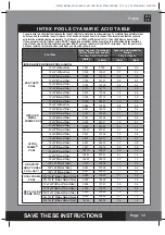
Page 14: ...2 640cm x 132cm 24 x 52 732cm x 132cm 16 x 48 488cm x 122cm 18 x 48 549cm x 122cm 18 x 52 549cm x 132cm 20 x 48 610cm x 122cm 22 x 52 671cm x 132cm 24 x 52 732cm x 132cm 26 x 52 792cm x 132cm 15 8 x 4...

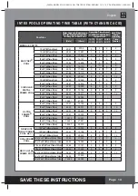
Page 15: ...m 18 x 48 549cm x 122cm 21 x 52 640cm x 132cm 24 x 52 732cm x 132cm 16 x 48 488cm x 122cm 18 x 48 549cm x 122cm 18 x 52 549cm x 132cm 20 x 48 610cm x 122cm 22 x 52 671cm x 132cm 24 x 52 732cm x 132cm...

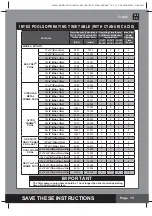
Page 16: ...025 Water Capacity Liters x 0 003 Water Capacity Gals x 0 0067 Water Capacity Liters x 0 0008 OPERATING TIME TABLE FOR COMMON NON INTEX POOLS WITH CYANURIC ACID CYANURIC ACID TABLE FOR COMMON NON INT...

Page 17: ...time each day for the number of hours you have set NOTE The Saltwater System will not operate if the filter pump is not operating Make sure to program your filter pump or start it manually for operat...

Page 18: ...ights up and the LED display flashes 93 The system is now in Stand By mode After a while it shuts down and sets itself in a Power Saving mode The system will automatically turn itself back on in 24 ho...

Page 19: ...g Hour 1 hour remaining 02 Operating Hours 2 hours remaining 03 Operating Hours 3 hours remaining 04 Operating Hours 4 hours remaining 05 Operating Hours 5 hours remaining 06 Operating Hours 6 hours r...

Page 20: ...in the conduit Now turn the collar in a clockwise motion tightening the sensor back into its position Do not overtighten Titanium and E C O Electrodes Cleaning The titanium electrode and E C O electr...

Page 21: ...ll 3 4 Unscrew the collar of the flow sensor 6 and pull out the flow sensor from the electrolytic cell 3 housing 5 Pour kitchen grade vinegar into the electrolytic cell 3 to immerse the titanium and E...

Page 22: ...label If necessary adjust the chemical level in the pool water It is very important to use the proper technique when testing the water s chemical level Read and follow the written strip instructions...

Page 23: ...H Result if too high Scale formation cloudy water eye skin irritation poor chlorine efficiency Calcium Hardness Refers to the amount of calcium and magnesium dissolved in the water Result if too high...

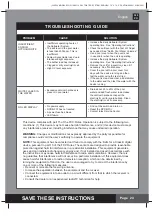
Page 24: ...ic cell if necessary Find out the switch and turn on Reset the RCD GFCI Contact Intex Service Center PROBLEM CAUSE SOLUTION This device complies with part 15 of the FCC Rules Operation is subject to t...

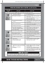
Page 25: ...ee Maintenance Release all trapped air in the circulation line See the filter pump manual Check the direction of the inlet and the outlet hose Reverse the hoses if necessary See Set Up Instructions Cl...

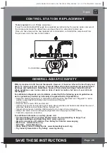
Page 26: ...is supervising pool users about potential pool hazards and about the use of protective devices such as locked doors barriers etc Instruct all pool users including children what to do in case of an eme...

Page 27: ...l be repaired or replaced at no charge Any and all disputes regarding the provisions of this Limited Warranty shall be brought before an informal dispute settlement board and unless and until the prov...

Reviews: