background image


8


6. Calibration 


The sensor calibration is performed initially with the aid of a water bucket. The fine calibration can be 
performed later, when the sensor system is hanging in the rainwater tank and the minimum and 
maximum water levels actually exist.


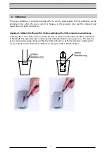
Important: Calibrate the 0% point first, before calibrating the 100% rainwater-level indicator. 

Submerge the sensor cable in water up to the 0% mark, at which point the cable should be stretched to 
its full length. Then press the lower, submerged 0% calibration button (using a pen, etc.). The value has 
been read when the display flashes briefly. The 100% calibration is performed similarly: Submerge the 
sensor cable up to the 100% mark and then press the upper 100% calibration button. 


Summary of Contents for RAINMASTER Eco-FS

Page 1: ...WATER WE RE IN OUR ELEMENT www intewa com RAINMASTER Eco FS Installation and user manual...

Page 2: ...ns and installation 4 5 1 Installation of display in Rainmaster Eco 4 5 2 Electrical connections in the RAINMASTER Eco 5 5 3 Electrical connections to the sensors 6 5 4 Installation of the sensors in...

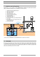
Page 3: ...tive measuring procedure permits the contactless recording of the current water level between the two sensor cables 1 7 6 13 9 11 10 13 12 8 2 3 4 5 System overview RAINMASTER Eco with RAINMASTER Eco...

Page 4: ...ed The operator is responsible for observing the safety and installation requirements Installations on the drinking water supply network must only be performed by an approved installation company 3 Sc...

Page 5: ...90 x 57 mm Operating voltage 15 V DC Sensor cable 2 x 4mm Length of sensor cable 3 m shorten up to 1 2m is permissible 5 Electrical connections and installation 5 1 Installation of display in RAINMAS...

Page 6: ...plug connection Connection for control board RM ECO with fill level indicator RM Eco FS via a flat cable plug Connection to the control board RM Eco Sensor 3 Control cable brown 15 V DC Sensor 2 Cont...

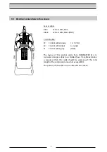
Page 7: ...V DC S2 Control cable black signal S1 Control cable grey GND The laying of the control cable from RAINMASTER Eco to rainwater storage is done in a shielded hose If a cable extension is required then...

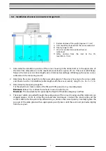
Page 8: ...r length from the lower cable gland of the sensor housing to the sensor cable end Shorten with a 7 cm addition cable length inside the sensor socket Length A B C 7 cm 3 Determine the measuring range B...

Page 9: ...Calibrate the 0 point first before calibrating the 100 rainwater level indicator Submerge the sensor cable in water up to the 0 mark at which point the cable should be stretched to its full length Th...

Page 10: ...r electronic circuit is faulty a Check connection and polarity at the sides of controller and sensor b Change sensor electronic circuits 0 10 and 90 100 LEDs both flashing simultaneously This indicato...

Page 11: ...D 24 SE3 Sensor cable 3 m 3 RMD 24 SK3 Control cable per m 4 RMD 24 STK 11 Contact For customers in Germany For any queries ordering of spare parts as well as in case of service kindly contact INTEWA...

Page 12: ...11 INTEWA GmbH Version 1 5b Subject to technical changes...

Reviews: