


21
NOTE: DIAGRAMS & ILLUSTRATIONS NOT TO SCALE.
Thermopile
TH
TP
TH
TP
Millivolt Wiring Diagram
If any of the original wire as supplied must be replaced, it
must be replaced with
Type AWM 105°C 18 GA. wire.
*OPTIONAL APPLIANCE-MOUNTED ON/OFF SWITCH,
OPTIONAL WALL-MOUNTED ON/OFF SWITCH,
OPTIONAL THERMOSTAT
OR OPTIONAL REMOTE CONTROL RECEIVER
Factory Wired
Field Wired
Schematic Representation Only
Figure 47
Note:
Secure Flex
vent must be attached to
Secure Flex
terminations only. DO NOT sub-
stitute
Secure Vent
terminations or the
Se-
cure Vent
adapter for
Secure Flex
compo-
nents. The collars of
Secure Flex
termina-
tions and adapters have a different diameter
than that used with the
Secure Vent
pipe.
Additionally,
Secure Flex
components have
an extended length center tube for use in
attaching the flexible vent.
Step 4. MILLIVOLT CIRCUIT WIRING
(
Figure 47
)
The gas valve is set in place and pre-wired at
the factory.
1
. Select any of the following optional
controls: appliance-mounted (rocker
switch) or wall-mounted switch, ther-
mostat, or one of the optional remote
control kits. If appliance-mounted ON/
OFF control is selected, mount it in the
gas valve mounting bracket.
2
. If wall-mounted ON/OFF control or ther-
mostat is selected mount it in a conve-
nient location on a wall near the fireplace.
3
. Wire the control within the millivolt con-
trol circuit using the 15 feet of 2 conduc-
tor wire supplied with the unit.
Caution: Do not connect the optional
wall switch to a 120V power supply.
4.
Alternatively, the appliance may be oper-
ated without the use of the controls indi-
cated in step 1, solely by manipulating
the gas valve control knob. In order to
use this method, twist the free ends of
the two conductor wire (located on top of
the unit) together as shown in
Figure 47
.
Note: The supplied 15 feet of 2 conductor
wire has one end of each conductor
connected to the gas valve circuit and the
other end of each conductor placed
loose on top of the unit.
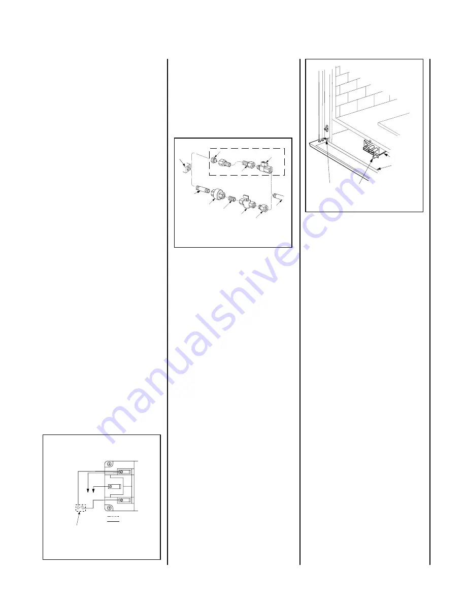
Gas Stub
¹₂
" x
³₈
" Flare
Shut-Off Valve
³₈
" Flex Tubing
³₈
" NPT x
³₈
"
Flare Fitting
³₈
" Nipple
³₈
"
Union
³₈
" Close Nipple
³₈
" Shut-Off Valve
¹₂
" x
³₈
" Reducer
Gas
Valve
Gas Flex Line Connector
Figure 49
Figure 48-
GAS CONNECTION
Turn on gas supply and test for gas leaks using
a soapy water solution.
Never use an open
flame to check for leaks
.
A.
Mix a 50% dish soap, 50% water solution.
B.
Light the appliance (refer to the lighting
instructions provided in the Homeowner's Care
and Operation Instructions).
C.
Brush all joints and connections with the
soapy water solution to check for leaks. If bubbles
are formed, or gas odor is detected, turn the gas
control knob to the “OFF” position. Either tighten
or refasten the leaking connection and retest as
described above.
D.
When the gas lines are tested and leak
free, observe the individual tongues of flame
on the burner. Make sure all ports are open
and producing flame evenly across the
burner. If any ports are blocked, or partially
blocked, clean out the ports.
Step 5
.
CONNECTING GAS LINE
Make gas line connections. All codes require a
shut-off valve mounted in the supply line.
Figure 48
illustrates two methods for con-
necting the gas supply. The flex-line method is
acceptable in the U.S., however, Canadian
requirements vary depending on locality. In-
stallation must be in compliance with local
codes.
These appliances are equipped with a gas flex
line for use (where permitted) in connecting
the unit to the gas line. A gas flex line is
provided to aid in attaching the direct vent
appliance to the gas supply. The gas flex line
can only be used where local codes permit.
See
Figure 48
for flex line description. The
flex line is rated for both natural and propane
gas. A manual shut off valve is also provided
with the flex line.
The gas control valve is located in the lower
control compartment. To access the valve
proceed as follows:
Secure all joints tightly using appropriate
tools and sealing compounds (ensure pro-
pane resistant compounds are used in pro-
pane applications).
The millivolt control valve has a
³⁄₈
"
(10 mm) NPT thread inlet port.
Open the control compartment access panel,
(Figure 49)
by actuating the spring-loaded
magnetic catches securing the panel, gently
depressing the outer top corners of the panel
until the catches "pop" the panel free and
allowing it to swing out and down to open.
Piezo Ignitor
Gas Valve
Control
Compartment
Access panel
Hinge Pin
f i r e - p a r t s . c o m


