2
AN1507.0
September 11, 2009
Functional Description
The ZL6100EVAL2Z provides all circuitry required to
demonstrate the features of the ZL6100. The
ZL6100EVAL2Z has a functionally-optimized ZL6100
circuit layout that allows efficient operation up to the
maximum output current. Power and load connections
are provided through plug-in sockets.
All features of the ZL6100 such as current sharing, soft-
start delay and ramp times, supply sequencing, voltage
tracking, and voltage margining are available on this
evaluation board. For voltage tracking, the board is set
up for the single phase rail (V
OUT2
) to track the dual
phase rail (V
OUT1
). Contact the Zilker Labs sales office
for configuring the board for other tracking combinations.
Figure 1 shows a functional block diagram of the
ZL6100EVAL2Z board. The SMBus address is selectable
through a jumper on the top side of the board. All power
to the board (VIN and I
2
C bus) must be removed before
changing the jumpers.
The hardware enable function is controlled by a toggle
switch on the ZL6100EVAL2Z board. The power good
(PG) LEDs indicate the correct state of PG when external
power is applied to the ZL6100EVAL2Z board. (Note: If a
USB board is connected to the ZL6100EVAL2Z and no
power is applied to the board, the PG LEDs will turn on
even though the power rails are not enabled.) The right
angle headers at opposite ends of the board are for
connecting a USB to SMBus adapter board or for daisy
chaining of multiple evaluation boards.
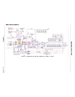
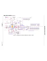
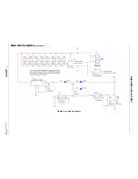
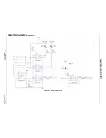
Figures 2 and 3 show the two phases of the 60A circuit.
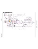
Figure 4 shows the single phase operational circuit. The
circuit consists of the ZL6100 IC with its minimal
component count to realize a 30A buck converter. The
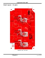
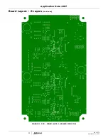
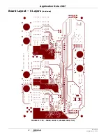
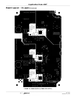
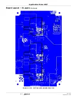
board layout has been optimized for thermal
performance.
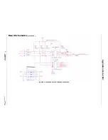
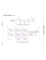
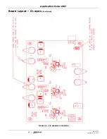
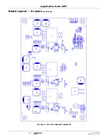
Figure 5 is the Interface and Figure 9 SMBus address
selection circuitry.
Operation
PMBus Operation
The ZL6100 utilizes the PMBus protocol. The PMBus
functionality can be controlled via USB from a PC running
the PowerNavigator evaluation software in a Windows XP
or Windows 2000/NT operating system.
Install the ZL6100EVAL2Z software using the CD
included in the ZL6100EVAL2Z kit.
For board operation, connect the included USB-to-SMBus
adapter board to J10 of the ZL6100EVAL2Z board.
Connect the desired load and an appropriate power
supply to the input and connect the included USB cable
to the PC running the PowerNavigator evaluation
software. Place the ENABLE switch in “DISABLE” and turn
on the power.
The evaluation software allows modification of all ZL6100
PMBus parameters. Each of the ZL6100 devices have
been pre-configured as described in this document, but
the user may modify the operating parameters through
the eval software or by loading a predefined scenario
from a configuration file.
Use the mouse-over pop-ups for PowerNavigator help.
Refer to Zilker Labs application note AN2033 “PMBus
™
Command Set DDC Products”, Intersil Corporation,
2009
for PMBus details.
The ENABLE switch can then be moved to “ENABLE” and
the ZL6100EVAL2Z board can be tested. Alternately, the
PMBus ON-OFF CONFIG and OPERATION commands may
be used.
Quick Start Guide
Stand Alone Operation
1. Set ENABLE switch to “DISABLE”
2. Apply load to VOUT+/VOUT- for each channel
3. Connect power supply to VIN+/VIN- (supply turned
off)
4. Turn power supply on
5. Set ENABLE switch to “ENABLE”
6. Monitor ZL6100EVAL2Z board operation using an
oscilloscope
USB (PMBus) Operation
1. Set ENABLE switch to “DISABLE”
2. Apply load to VOUT+/VOUT- for each channel
3. Connect power supply to VIN+/VIN- (supply turned
off)
4. Turn power supply on
5. Insert the Zilker Labs Eval Kit CD
6. Connect USB to SMBus adapter board to J10 of
ZL6100EVAL2Z
7. Connect supplied USB cable from computer to USB
to SMBus adapter board
a) Upon first-time connection, the Found New
Hardware Wizard will appear.
b) Windows XP users: Select ‘No’ at prompt to
search the Internet for drivers.
c) Follow the steps on the screen to install the
drivers from the CD.
8. Install the PowerNavigator evaluation software by
running setup.exe from the
PowerNavigator_installer folder on the CD.
9. Set ENABLE switch on EVB to “ENABLE”
10.Monitor and configure the ZL6100EVAL2Z board
using PMBus commands in the evaluation software
11.Test the ZL6100EVAL2Z operation using an
oscilloscope and the evaluation software.
Application Note 1507


