UG074 Rev.2.00
Page 4 of 17
Nov 14, 2018
ISL9238EVAL1Z
Charging Mode
1. Set the power supply to a constant value between 3.8V and
24V, then complete Steps 1 and 2 in
. Make sure the input current does not
reach the limit.
2. Set the battery emulator voltage to 7.8V and connect the
battery emulator output to battery leads J5 and J6.
3. Connect the USB cable at the USB port for the SMBus. LED 1,
2, and 3 all turn on.
4. Turn on the power supply; LED 3 turns off. Turn on the battery
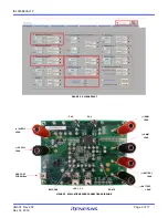
emulator and open the ISL9238 GUI (shown in
)
.
Note: A green check mark
in the USB Interface section of
the GUI indicates the GUI is ready to communicate with the
evaluation board. A red X
in the USB Interface section
indicates the GUI is not ready to communicate with the
evaluation board. Click the Reset USB button until a green
check mark shows in the USB Interface. If a green check mark
does not appear, check the USB connection.
5. Select 2 Cell in the Battery Cell Configuration section and
click the Write All button. All controller register values are set
to the default values correspondingly. The system voltage is
8.4V, which is the value of MaxSysVoltage in the GUI. There is
no charge and discharge current for the battery.
6. Change the ChargeCurrentLimit from 0A to 2A and click the
Write button. The battery is now in a 2A current charge
configuration. The charge current value can be monitored in
the GUI by clicking the Read button in the ChargeCurrentLimit
section
.
Monitor the BGATE signal status to confirm the
battery is in Charging mode.
Note: Make sure the input current does not reach the input
current limit value, especially for a small V
IN
input.
Trickle Charging Mode
1. Complete Steps 1 through 6 in
without any
changes.
2. Decrease the battery emulator voltage and monitor the
battery charging current. As long as the battery emulator
voltage is less than 5.2V (lower than SystemMinVoltage), the
battery enters trickle Charging mode and the charge current
decreases to 0.26A. The trickle charge current value can be
changed through the SMBus control registers. Refer to the
datasheet for more information.
Note: Make sure the input current does not reach the input
current limit value, especially for small V
IN
input.
OTG Mode
1. Set the battery emulator voltage to a constant value between
5.8V and 15V. Connect battery leads J5 and J6 with the output
disabled.
2. Connect the electric load on supply leads J1 and J2 with the
output disabled.
3. Connect the USB cable at the USB port for SMBus. Only the
LED 1 light is on. Turn on the battery emulator and electrical
load without adding any load.
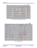
4. Open the ISL9238 GUI. The OTGVoltage is the voltage value
for the load side, as shown in
. The
OTGCurrent is the OTG output current limit at the load side.
These values can be set as needed within the output limit
range. Refer to the
datasheet for the OTGVoltage
and OTGCurrent value ranges.
5. Select the Control0 & 1 Registers tab, enable the OTG
function in Control1 Register, and click the Write button, as
shown in
6. Switch SW2 on the evaluation board to the HI position. The
load voltage is regulated as an OTGVoltage value, set in
, and the LED 3 light is on, indicating the
OTG function is enabled.
7. Increase the electrical load slowly and monitor the load
voltage. As long as the load current is less than the
OTGCurrent limit value, the load voltage is regulated at the set
value.


