UG074 Rev.2.00
Page 2 of 17
Nov 14, 2018
ISL9238EVAL1Z
Recommended Equipment
• 0V to 25V power supply with at least 6A source current capability
• Electronic load capable of sinking current up to 6A
• Battery emulator capable of sinking and sourcing current up to
6A
• Digital Multimeters (DMMs)
• 100MHz quad-trace oscilloscope
NOTE: You can use a power supply (that can source current but cannot
sink current) in parallel with an e-load Constant Current (CC) mode to
emulate the battery. For example, to charge, set the charging current
command lower than the CC mode e-load. If the e-load CC mode current
is set to 3A, the charge current command is 2A, and the e-load takes 2A
from the charger and takes another 1A from the power supply in parallel
with it. To discharge, the power supply acts like the battery to discharge
current. You can also use the e-load Constant Voltage (CV) mode to
emulate the battery to take the charging current from the charger and set
the e-load CV voltage below the MaxSysV register setting; however, this
e-load CV mode cannot source current like a battery.
Functional Description
The ISL9238EVAL1Z provides all circuits required to evaluate the
features of the ISL9238. A majority of the features of the
ISL9238, such as adjustable output voltage, On-the-Go (OTG)
mode, Trickle Charging mode for depleted battery, and system
power monitor at Buck, Boost, and Buck-Boost modes are
available on this evaluation board.
Quick Start Guide
The number of battery cell and adapter current limit default
values can be configured with a standard 1% 0603 resistor (R
23
)
from the PROG pin to GND. The “PROG PIN PROGRAMMING
OPTIONS” table in the
datasheet shows the
programming options. After the default number of cells in series
is set, the default values for MaxSystemVoltage and
MinSystemVoltage are set accordingly. These values can also be
changed through the SMBus control registers in the Renesas GUI,
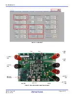
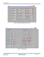
shown in
The three LEDs indicate the ACOK, PROCHOT, and
OTGPG/CMOUT status, respectively. For more details about the
functions of these three pins, refer to the
datasheet.
Complete the following steps to evaluate the ISL9238 key
functions
,
including system voltage regulation, input current limit
regulation, Charging mode, trickle Charging mode, and OTG
mode.
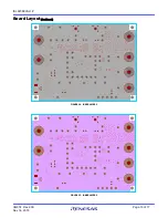
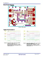
shows the top view of the evaluation board and
highlights the key testing points and connection terminals. For
more information about the ISL9238, including other modes of
operation, refer to the
datasheet.
System Voltage Regulation
1. Set the power supply to 5V. Disable the output and connect
the (+) end to J1 and the (-) end to J2.
2. Ensure jumpers JP3, JP4, and JP6 are shorted. SW1 and SW2
should switch to the low position.
3. Turn on the power supply and measure VSYS using the DMM
across (+) and (-) TP5. VSYS should read 8.38V. The current
meter on the supply should read <100mA
.
Slowly increase
V
IN
from 5V to 15V. Monitor PH1 and PH2 to observe
seamless switching from Boost mode to Buck-Boost mode
and finally into Buck mode.
Input Current Limit Regulation
1. Keep V
IN
as a constant value between 3.8V and 24V. Set the
battery emulator voltage to 7.8V and connect the battery
emulator output to battery leads J5 and J6. Turn on the
battery emulator; there is no charge and discharge current for
the battery, which is consistent with the BGATE signal of a
high voltage level.
2. Add an electrical load on VSYS and GND terminals J3 and J4.
Turn on the load and increase the electrical load slowly; the
input current increases correspondingly and VSYS keeps
stable at 8.38V. The output voltage (VSYS) starts dropping as
the input current reaches the 1.5A input current limit. Refer
to the
datasheet for more information about the
input current limit. If the VSYS voltage is 150mV lower than
the battery voltage, the BGATE FET turns on at a low voltage
level so that the battery supplies the current to the load.


