background image

Application Note 1655

3

AN
16

5

5

.0

Au

gust 1

8

, 20
1

1

ISL8200MEVAL1PHZ Schematic

86( *50%5$.(/ 8) 

9287

,6/0(9$/3+=

.,5$1 %(51$5'

.,5$1 %(51$5'

&

*1'

39,1

*1'

TP34

39,1

H

EAD

ER

1

12

J2

J1

R203

C

210

C

209

8)

3)

C211

R2

0

6

3+$6(

17

(1B%86

16

14

15

7%'

C212

2

8)

1

))B%86

R211

'13

2

39,1

VCC_PWR

39,1

C251

C231

8)

8)

8)

C230

C207

7%'

7%'

8)

C250

C233

8)

8)

C232

7%'

C205

C206

C203

8)

8)

18

11

10

8

9

7

5

4

3

19

C202

C201

8)

9287

1

2

23

22

21

20

&/.

'13

C235

7%'

,6)

(7

'

5

9

7%'

2

C9

2

C1

9

8

)

9287

1

1

2

R

241

1

AD

J

1

2

31

.

R

2

09A

'13

12

FI

XED

3*22'

9&&

R

221A

1

1.2V

2

.

R

221B

1

.

1.5V

2

1.8V

R

221C

C

234

3+$6(

8)

1

.

2

VSEN+

C

001

3

)

R

219

'13

R

221D

.

1

R

221E

.

R

221F

1

3.3V

2.5V

5.0V

2

2

C2

4

7%'

C5

1

8

)

7%'

C2

5

7%'

C1

2

2

1

.

2

1

1

.

3

AD

J

2

C

204

R221_ADJ

RM+2

9287

3

)

RM-2

7%'

8

)

C

252

C

253

8

)

VSEN-

8

)

8

)

C

255

C

254

VSEN+_PRIME

J4

LED301

1

3*22'

VOUT

1

TP301

1

2

2

4

3

Q302

1

1

R

325

9&&

.

3

R

324

.

TP

310

66/B/;$,*&

C3

&/.

8)

13

12

,6)(7'59

(1B%86

2

1

R1

R4

R3

'13

SW1

3

'13

.

.

1

C15

8)

2

R2

R

223

6

U1

,6/0,5=

.

R217

.

R215

R2

4

0

1

JP201

C236

2

1

VCC

PVIN

9&&

VCC_GND

))B%86

PVIN_TP

RE

D

GR

N

ISET

IS

HA

RE

VSEN

_

R

EM

-

VOU

T

SET

IS

FETD

R

V

OCSET

PVI

N

PHASE

CL
K

O

UT

PGND1

PVCC

VIN

NC

PGOOD

VCC

VOUT

PGND

IS

HA

RE

_

B

US

F

S

Y

NC_

IN

EN

P

H

_

CNTRL

FF

P

G

ND1

12

RELEASED BY:

DRAWN BY:

SHEET

HRDWR ID

DATE:

DATE:

DATE:

TESTER

FILENAME:

MASK#

REV.

OF

DATE:

ENGINEER:

TITLE:

UPDATED BY:

10

U

F

Summary of Contents for ISL8200MEVAL1PHZ

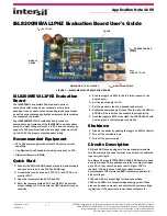
Page 1: ...T 3 Open the jumpers marked PVIN and VCC 4 Short the jumpers marked 1 2V and FIXED This sets the output voltage to 1 2V and sets the OCP trip point its open condition 5 Push the toggle on SW1 to the left with respect to the board above 6 Set the input supply to 12V 7 Set the electronic load to a desired load current 8 Enable the power supply first and then the load the LED for PGOOD will be red wh...

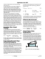
Page 2: ...VLO and its hysteresis can be programmed The ISL8200MEVAL1PHZ evaluation board comes stocked with R1 8 25kΩ and R2 3 01kΩ this sets the UVLO level at 2 9V for a 3 3V application For a 5V application with a UVLO at 4V and recover at 4 5V use R1 16 6kΩ and R2 4 2kΩ The UVLO equations are re stated in the following where R1 and R2 are the upper and lower resistors of the voltage divider at the EN pin...

Page 3: ...V 2 1 8V R221C C234 3 6 8 1 2 VSEN C001 3 R219 13 R221D 1 R221E R221F 1 3 3V 2 5V 5 0V 2 2 C24 7 C51 8 7 C25 7 C12 2 1 2 1 1 3 ADJ 2 C204 R221_ADJ RM 2 9287 3 RM 2 7 8 C252 C253 8 VSEN 8 8 C255 C254 VSEN _PRIME J4 LED301 1 3 22 VOUT 1 TP301 1 2 2 4 3 Q302 1 1 R325 9 3 R324 TP310 66 B C3 8 13 12 6 7 59 1B 86 2 1 R1 R4 R3 13 SW1 3 13 1 C15 8 2 R2 R223 6 U1 6 0 5 R217 R215 R240 1 JP201 C236 2 1 VCC P...

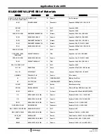
Page 4: ... TDK Capacitor 10µF 20 25V 1210 C24 C51 C205 C207 4 DNP Capacitor 1210 C3 C15 35MV270AX 2 Sanyo Capacitor 270µF 20 35V Radial C9 C19 2TPLF330M7 2 Sanyo Capacitor 330µF 20 2V SMD HEADER1 TSW 102 07 L S 1 Generic 2 Pin Header J1 111 0702 001 1 JOHNSON COMP Binding Post Red J2 111 0703 001 1 JOHNSON COMP Binding Post Black J4 VOUT KPA8CTP 2 Burndy Wire Connector Lug LED301 SSL LXA3025IGC 1 Lumex 3 5m...

Page 5: ...eter 100kΩ 20 0 125W SMD R3 R4 H2505 DNP DNP 1 2 DNP Resistor 0603 R324 R325 H2505 03301 1 16WR1 2 Generic Resistor 3 3kΩ 0 1 1 16W 0603 SW1 GT11MSCBE T 1 C K Switch SPDT Toggle TP301 VSEN VSEN VSEN_PRIME 5002 4 Keystone Miniature White Test points 0 100 pad with 0 040 t hole TP34 TP310 PVIN_TP VCC_GND VDD_PWR 1514 2 5 Keystone Test point Turret 0 150 pads with 0 100 t hole U1 ISL8200MIRZ 1 Inters...

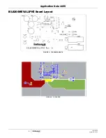
Page 6: ...Application Note 1655 6 AN1655 0 August 18 2011 ISL8200MEVAL1PHZ Board Layout FIGURE 3 TOP COMPONENTS FIGURE 4 TOP LAYER ...

Page 7: ...Application Note 1655 7 AN1655 0 August 18 2011 FIGURE 5 2nd LAYER FIGURE 6 3rd LAYER ISL8200MEVAL1PHZ Board Layout Continued ...

Page 8: ... without notice Accordingly the reader is cautioned to verify that the Application Note or Technical Brief is current before proceeding For information regarding Intersil Corporation and its products see www intersil com AN1655 0 August 18 2011 FIGURE 7 BOTTOM LAYER FIGURE 8 BOTTOM COMPONENTS MIRRORED ISL8200MEVAL1PHZ Board Layout Continued ...

Page 9: ...Mouser Electronics Authorized Distributor Click to View Pricing Inventory Delivery Lifecycle Information Intersil ISL8200MEVAL1PHZ ...

Reviews: