IRDC3863
IR WORLD HEADQUARTERS:
233 Kansas St., El Segundo, California 90245, USA Tel: (310) 252-7105
TAC Fax: (310) 252-7903
Visit us at www.irf.com for sales contact information
Data and specifications subject to change without notice. 06/2011
15
Page 1: ...instructions of the IRDC3863 evaluation board Detailed product specifications application information and performance curves at different operating conditions are available in the IR3863 data sheet Th...
Page 2: ...s should be applied to these inputs VCC input should be a well regulated 4 5V to 5 5V supply connected to VCC and PGND Enable EN is controlled by the first switch of SW1 and FCCM option can be selecte...
Page 3: ...IRDC3863 3 CONNECTION DIAGRAM Fig 1 Connection Diagram of IRDC3863 Evaluation Board VIN GROUND VOUT 1 05V GROUND VCC 5 0V EN FCCM Control Switch for GROUND...
Page 4: ...IRDC3863 4 Fig 2 Board Layout Top Components PCB Board Layout Fig 3 Board Layout Bottom Components...
Page 5: ...IRDC3863 5 Fig 4 Board Layout Top Layer Fig 5 Board Layout Bottom Layer PCB Board Layout...
Page 6: ...IRDC3863 6 Fig 6 Board Layout Mid layer I Fig 7 Board Layout Mid layer II PCB Board Layout...
Page 7: ...NC2 9 PGND 11 PHASE 12 EN 16 C4 0 22uF VCC TP4 EN SW1 EN FCCM 1 2 4 3 TP17 PGND C20 0 1uF TP26 AGND VSW C21 1uF TP11 PGOOD R9 open L1 2 2uH R6 open TP1 VINS R4 10K R3 200K C13 open C2 22uF C16 open C3...
Page 8: ...IRDC3863 8 Bill of Materials...
Page 9: ...1V div 500mV div 5ms div 5V div 5V div 1V div 500mV div 1ms div Fig 11 DCM IOUT 0 1A Fig 12 CCM IOUT 5A VOUT PHASE iL VOUT PHASE iL 20mV div 10V div 500mA div 5 s div 20mV div 10V div 2A div 2 s div P...
Page 10: ...airflow unless otherwise specified Fig 15 Load Transient 0 2A Fig 16 Load Transient 3 5A VOUT PHASE iL VOUT PHASE iL 50mV div 10V div 2A div 50 s div 50mV div 10V div 2A div 50 s div TYPICAL PERFORMAN...
Page 11: ...n Fig 21 Line Regulation at 6A Load 1 040 1 045 1 050 1 055 1 060 1 065 1 070 1 075 1 080 1 085 1 090 0 1 2 3 4 5 6 Load Current A Output Voltage V 1 040 1 045 1 050 1 055 1 060 1 065 1 070 1 075 1 08...
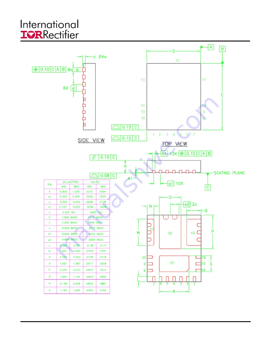
Page 12: ...should be equal to maximum part lead length 0 3 mm outboard extension The outboard extension ensures a large toe fillet that can be easily inspected Pad lands the 4 big pads length and width should be...
Page 13: ...m of 0 025mm to ensure NSMD pads The land pad should be Solder Mask Defined SMD with a minimum overlap of the solder resist onto the copper of 0 05mm to accommodate solder resist misalignment Ensure t...
Page 14: ...ences of lead shorts If too much solder is deposited on the center pad the part will float and the lead lands will open The maximum length and width of the land pad stencil aperture should be equal to...
Page 15: ...HEADQUARTERS 233 Kansas St El Segundo California 90245 USA Tel 310 252 7105 TAC Fax 310 252 7903 Visit us at www irf com for sales contact information Data and specifications subject to change without...