background image

IRDC3847-P1V2

4/11/2013

12

THERMAL IMAGES
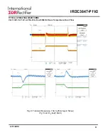
Vin=12.0V, Vo=1.2V, Io=0A-25A, Fsw=600kHz, Room Temperature, No air flow

Fig. 13: Thermal Image of  the board at 25A load

Test point 1 is IR3847: 75

0

C

Test point 2 is inductor: 61.5

0

C

Summary of Contents for IR3847

Page 1: ...zation with smooth clocking internal LDO true differential remote sensing and pre bias start up A thermally compensated output over current protection function is implemented by sensing the voltage de...

Page 2: ...d be removed for this purpose CONNECTIONS and OPERATING INSTRUCTIONS LAYOUT The PCB is a 6 layer board All of layers are 2 Oz copper The IR3847 and most of the passive components are mounted on the to...

Page 3: ...re located close to IR3847 The feedback resistors are connected to the output of the remote sense amplifier of the IR3847 and are located close to the IR3847 To improve efficiency the circuit board is...

Page 4: ...N S R32 4 22K C36 N S Vcc 1 C34 N S D2 N S 1 2 C51 N S D3 N S 1 2 PVin Vsns R18 49 9K C1 330uF R29 10K R33 0 C27 47uF C8 2200pF U3 IR3847 Vin 17 LGnd 11 Rt Sy nc 4 SW 22 Vcc 18 Comp 8 Vsns 6 PGnd 26 O...

Page 5: ...N S R23 N S R24 N S R25 N S ExtLoadCtrl 1 M1 IRF6721 N S U2 MIC4452 SO8 N S VS 1 IN 2 GND 4 GND 5 OUT1 6 OUT2 7 VS 8 N A 3 R36 N S R37 N S S3 SW 2 1 3 C47 N S C49 N S R39 N S Vout C48 N S C63 N S Vo_...

Page 6: ...sonic ERJ 3EKF4221V 11 1 R3 4 22K 0603 1 10W 1 Panasonic ERJ 3EKF4221V 12 1 R4 127 0603 1 10W 1 Panasonic ERJ 3EKF1270V 13 1 R6 20 0603 1 10 W 1 Vishay Dale CRCW060320R0FKEA 14 1 R9 39 2K 0603 1 10 W...

Page 7: ...nductor node at 25A load Ch2 LX Fig 3 Start up at 25A Load Ch1 Vin Ch2 Vo Ch3 PGood Ch4 Vcc Fig 2 Start up at 25A Load Ch1 Vin Ch2 Vo Ch3 PGood Ch4 Enable Fig 4 Start up with 1 08V Pre Bias 0A Load Ch...

Page 8: ...RDC3847 P1V2 4 11 2013 8 TYPICAL OPERATING WAVEFORMS Vin 12 0V Vo 1 2V Io 2 5A 12 5A Fsw 600kHz Room Temperature No air flow Fig 8 Transient Response 2 5A to 12 5A step 2 5A us Ch2 Vout Ch4 Iout 10A V...

Page 9: ...IRDC3847 P1V2 4 11 2013 9 TYPICAL OPERATING WAVEFORMS Vin 12 0V Vo 1 2V Io 15A 25A Fsw 600kHz Room Temperature No air flow Fig 9 Transient Response 15A to 25A step 2 5A us Ch2 Vout Ch4 Iout 10A V...

Page 10: ...IRDC3847 P1V2 4 11 2013 10 TYPICAL OPERATING WAVEFORMS Vin 12 0V Vo 1 2V Io 0A 25A Fsw 600kHz Room Temperature No air flow Fig 10 Bode Plot at 25A load Fo 108 0kHz Phase Margin 50 2...

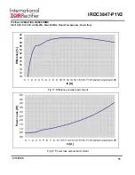
Page 11: ...EFORMS Vin 12 0V Vo 1 2V Io 0A 25A Fsw 600kHz Room Temperature No air flow 0 0 0 5 1 0 1 5 2 0 2 5 3 0 3 5 4 0 4 5 5 0 0 1 2 3 4 5 6 7 8 9 10 11 12 13 14 15 16 17 18 19 20 21 22 23 24 25 Power Loss W...

Page 12: ...P1V2 4 11 2013 12 THERMAL IMAGES Vin 12 0V Vo 1 2V Io 0A 25A Fsw 600kHz Room Temperature No air flow Fig 13 Thermal Image of the board at 25A load Test point 1 is IR3847 750C Test point 2 is inductor...

Page 13: ...3 IR WORLD HEADQUARTERS 233 Kansas St El Segundo California 90245 USA Tel 310 252 7105 TAC Fax 310 252 7903 Visit us at www irf com for sales contact information Data and specifications subject to cha...

Reviews: