


2
443 06 4003 00
Specifications subject to change without notice.
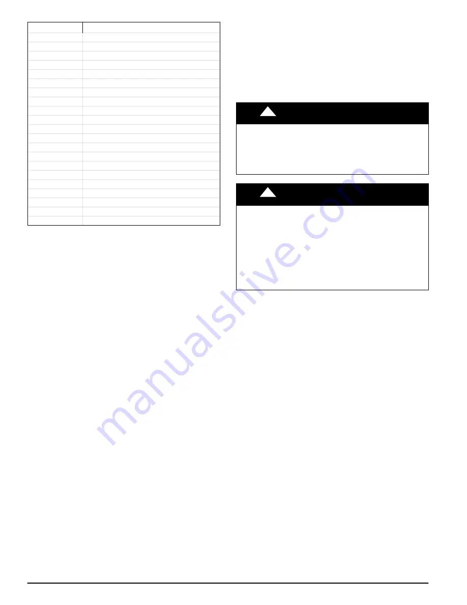
Table 1
Kit Contents
Qty.
Description
1
Adjustment Tool
1
Drill Bit 7/64”
1
Gas Valve
1
Connector 1/8” NPT
1
Elbow, Street Brass 1/8” NPT
1
Elbow, Street 150# 1/8” NPT
1
Tee, Street Brass
1
Tee Brass
1
Nipple HEX Brass
7
Screw HEX HD 8AB 3/4
1
Pressure Switch
1
Wire Tie
7
Orifice 1.25mm
1
Wire Assembly
1
Wire Assembly
1
Installation Label 322236
−
101
1
Adhesive Pouch 337985
−
101
1
Label, Conversion 340323
−
101
1
Conversion Rating Plate 340306
−
101
1
Instructions
DESCRIPTION AND USAGE
This kit is designed for use in the furnaces listed in the
Introduction. This kit is required for furnaces that use natural
gas or propane gas. These instructions describe the
modifications required for use in a manufactured (mobile)
home. See
This conversion uses a White
−
Rodgers 36J convertible (natural
or propane) gas valve. More parts are shipped in the kit than
will be needed to complete the conversion. When installation is
complete, the extra parts are to remain with the furnace for
future use.
This furnace must be installed in accordance with the
manufacturer’s instructions and Manufactured Home
Construction and Safety Standard, Title 24 CFR, Part 3280 or,
when such standard is not applicable, the ANSI A225.1,
Standard for Manufactured Home Installation (Manufactured
Home Sites, Communities and Set
−
Ups), or the Mobile Homes
Standard CAN/CSA
−
Z240 MH Series
−
09.
Ce générateur d’air chaud doit être installé conformément avec
les instructions du fabricant et la norme intitulée Manufactured
Home Construction and Safety Standard, Title 24 CFR, Part
3280 ou, lorsque cette norme ne s’applique pas, la norme ANSI
A225.1, intitulée Standard for Manufactured Home Installation
(Manufactured Home Sites, Communities and Set
−
Ups), ou la
norme CAN/CSA
−
Z240 MH Série 09 de I’ACNOR, intitulée
Maisons mobiles.
This furnace must be installed as a direct
−
vent/2
−
pipe
(combustion air and flue) system. In a direct
−
vent system, all
air for combustion is taken directly from the outside
atmosphere, and all flue products (exhaust) are discharged to
the outside atmosphere. See furnace and factory accessory
concentric vent instructions for proper installation.
NOTE
: The factory accessory concentric vent when used for
sidewall termination MUST NOT project more than 3
−
in. (76
mm) beyond the surface of the wall. See the appropriate
section for installation modification.
SECTION I
: Initial Kit Installation
SECTION II
: Conversion from Natural Gas to Propane
SECTION III
: Conversion from Propane to Natural Gas
SECTION I: INITIAL KIT INSTALLATION
Procedure 1 — General
A downflow furnace application is where furnace blower is
located above combustion and controls section of furnace, and
conditioned air is discharged downwards.
Attach adhesive pouch containing literature packet and gas
conversion parts to outside of main furnace door or accessible
side of furnace for use at a later date. (See
!
WARNING
PERSONAL INJURY AND UNIT DAMAGE HAZARD
Failure to follow this warning could result in personal injury or
unit damage.
When installing the air conditioning coil casing or when
servicing air conditioning, caution must be taken to ensure
furnace will not fall forward.
!
CAUTION
UNIT DAMAGE HAZARD
Failure to follow this caution may result in damage to the unit.
To prevent damage during transportation of the home, coil
casing must be secured to the floor, furnace and coil casing
must be fastened together, and furnace must be secured to
wall of the structure. When a coil casing is not used, an
accessory floor base is required. (See furnace rating plate or
clearance label for special accessory floor base part
number.) Secure floor base to structure and attach furnace to
floor base.
RECOMMENDED METHODS OF SECURING
FOR TYPICAL INSTALLATION
All mounting hardware is field
−
supplied.
1. Secure coil casing to floor.
a. Secure coil casing to floor of structure using 5/16
−
in.
(8 mm) lag screws (one each side) through lower
inside flanges of coil casing.
b. Alternate method: Attach right angle mounting
brackets or pipe strap (bent 90 degrees) to coil
casing using No.10 self tapping screws. Attach other
end of brackets/strap to floor of structure using
5/16
−
in. (8 mm) lag screws. If coil is present in
casing, be careful not to damage condensate pan
with tip of screw or remove coil from casing.
2. Fasten furnace to coil casing. Be careful not to damage it
with tip of screw.
a. Secure furnace to coil casing using two (2) No.10 self
tapping screws (one on each side of burner
enclosure) through cell panel flange, lower furnace
casing plate, and coil casing top flange.
b. Alternate method: Attach pipe strap to both furnace
casing and coil casing (one each side).
3. Secure furnace to structure.
a. Attach pipe strap to top of furnace casing using
No.10 self
−
tapping screws. Angle strap down and
away from back of furnace, remove all slack, and
fasten to wall stud of structure using 5/16
−
in. (8 mm)
lag screws. Typical both sides of furnace.
b. Alternate method: Secure furnace to wall stud using
1/8
−
in. (7 mm) thick right
−
angle brackets. Attach
brackets to furnace using No.10 self tapping screws,
and to wall stud using 5/16
−
in. (8 mm) lag screws.


