


9
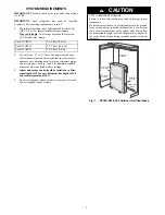
ATTACH THE REMOTE CONTROLLER MOUNTING
BRACKET
1. Use the two screws supplied with the controller to attach
the mounting bracket to the wall in the location selected
by the customer (see Fig. 10).
2. Install batteries in the remote control.
3. Place remote control into remote control mounting brack-
et.
4. For remote control operation, refer to the unit Owner’s
Manual.
REMOTE CONTROL
REMOTE CONTROL
MOUNTING BRACKET
Fig. 10
—
Attach Mounting Bracket to the Wall
(OPTIONAL)
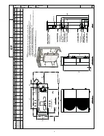
NADA001TW
Fig. 11
—
Wall Mounted Unit – RTX
Outdoor Unit Installation
NOTE
: The outdoor unit must be installed on a solid surface
(mounting base).
1. Place the rubber absorption cushions (supplied with the
outdoor unit) under the unit’s feet to prevent vibrations.
2. Fasten the outdoor unit legs to the mounting base, as
shown in Fig. 12. The cushion goes between the legs and
the mounting base.
3. Be sure that the unit is leveled.
MAKE REFRIGERANT PIPING CONNECTIONS (OUT-
DOOR UNIT) — To connect the refrigerant lines:
Make sure to properly identify and separate between the piping
and control cables coming from indoor unit No. 1 and the piping
and cables coming from indoor unit No. 2
Use only ”L” type sealed, dehydrated copper refrigerant tubing.
No other type of tubing may be used. Use of other types of tubing
will void the manufacturer’s warranty.
Do not open service valves or remove protective caps from
tubing ends until all the connections are made.
Bend tubing with special bending tools to avoid the formation of
sharp bends. Take care to avoid kinks or flattening of the tubing.
Keep the tubing free of dirt, sand, moisture, and other
contaminants to avoid damaging the refrigerant system.
Avoid sags in the suction line to prevent the formation of oil
traps.
Insulate each tube with 3/8
−
in. walled thermal pipe
insulation. Inserting the tubing into the insulation before
making the connections will save time and improve
installation The suction and mixed
−
phase lines should never
come in direct contact.
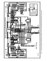
4 ABSORPTION CUSHION TO
BE PUT UNDER EACH LEG
INTER UNIT
TERMINAL BLOCK
N L1
115 VAC
1
2
3
4
5
24 V
AC
FAN (H)
FAN (L)
R.V.S
COMP.
COMMON
1
2
3
4
5
24 V
AC
FAN (H)
FAN (L)
R.V.S
COMP.
COMMON
1
2
METAL CONDUIT
CONNECTION PLATE
1
2
3
4
5
24 V
AC
FAN (H)
FAN (L)
R.V.S
COMP.
COMMON
TH3 SENSOR
(HEAT PUMP ONLY)
POWER SUPPLY
CABLE
INTER UNIT CABLE
N L1
115 VAC
1
2
3
4
5
24 V
AC
FAN (H)
FAN (L)
R.V.S
COMP.
COMMON
1
2
3
4
5
24 V
AC
FAN (H)
FAN (L)
R.V.S
COMP.
COMMON
1
2
HIGH/LOW
VOLTAGE METAL
BARRIER
POWER SUPPLY
TERMINAL BLOCK
Fig. 12
—
Legs Mounting Base and Wiring Outdoor
Units
Models: DFC2A/H318J2A, DFC2A/H324J2A