
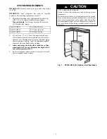


10
OFF ON
TIMER
IR RECEIVER
FILTER
PLASTIC CONTROL
COVER
SERVICE LED
Operation push button for
automatic operation (23
°
C/73
°
F),
turning the a/c OFF, canceling
the malfunction indication,
and resetting the filter LED.
INDOOR UNIT
2 X 09, 2 X 12
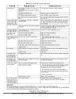
Fig. 12A — Indoor unit LED’s and Wiring
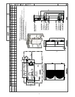
FLARING AND CONNECTING REFRIGERANT LINES
1. Remove the protective cap from the flare fitting.
2. Remove the protective cap from the tubing and cut to the
required length. Be sure that the cut is perpendicular and
clean, without burrs.
3. Slip the flare nut on the tubing and flare the tube end using
standard flaring tools.
4. Tighten the nut until resistance is met. Mark the nut and
the fitting. Using a suitable wrench tighten an additional
¼
turn. Use the following specified torque, according to con-
nection size:
Mixed
−
Phase line:
Suction line:
1/4 in.
−
(12.3 ft
−
lb.) 1/2 in.
−
(36 ft
−
lb.)
Both refrigerant lines need to be insu-
lated separately
NOTE
: The service valves on the outdoor unit must remain
closed until all 4 connections have been made.
EVACUATE TUBING AND CHARGE THE SYSTEM —
When all the fittings are connected, air must be expelled, then
refrigerant charge must be checked and adjusted. Follow the steps
below.
1. Open the service port cap on the suction line valve (large
valve of unit No. 1).
2. Connect the vacuum pump to the service port of unit No.
1 via the pressure gage and evacuate to 500 microns to
eliminate contamination and moisture.
3. Disconnect the vacuum pump. Unit should maintain 500
microns for 5 minutes.
4. Remove the service port caps from the mixed
−
phase valve
and suction line valve
5. Open the mixed
−
phase valve (small valve) with an Allen
wrench.
6. Open the suction line valve (large valve) with an Allen
wrench.
7. To evacuate and charge unit No. 2 repeat steps 1 thru 6.
8.
The outdoor unit is supplied with sufficient R
−
22 re-
frigerant for up to 25 ft. lineset length. Add 0.9 oz. of
refrigerant for each additional 3 ft. of tubing length.
9. Make sure that the valves are properly opened. Be careful
not to open them more than required as this may damage
the thread.
10. Replace the service port cap. Using refrigerant oil, lubri-
cate the cap beam and hand tighten until resistance is met.
Use a suitable wrench to tighten the cap by an additional
1/2 turn.
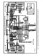
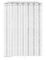
Power Supply
— See Tables 4 and 5 for electrical data and Fig.
13
−
14 for system wiring diagrams.
Leak Test
— Leak test all fittings with appropriate test
equipment.