background image


20 

TruVision 11/31 Series IP Camera Configuration Manual 

2.  Click 

Search

 to search the online wireless connections. 

3.  Click to choose a wireless connection on the list. 

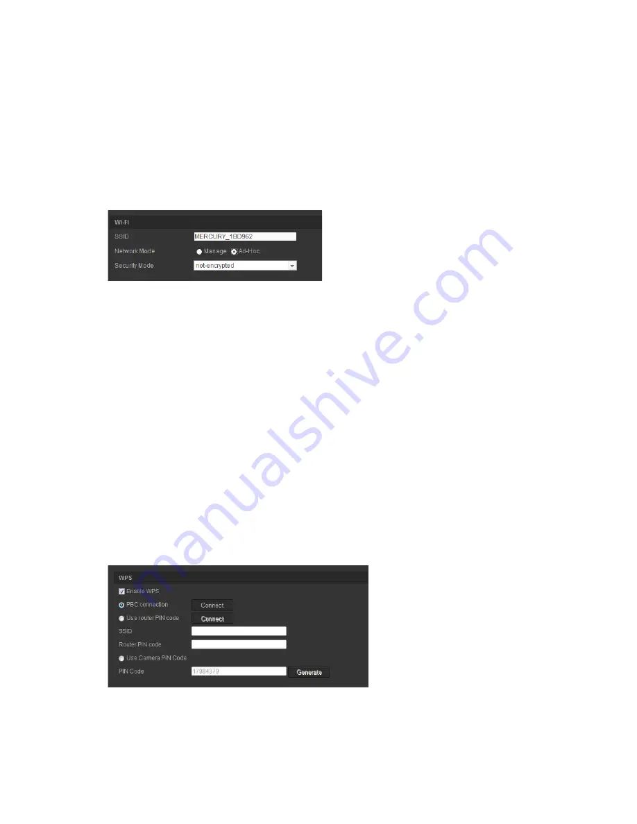
4.  Select the Network Mode as 

Manage

 or 

Ad-hoc


In 

Manage mode

, the Security Mode of is automatically shown when you 

select a wireless connection from the list. 

Ad-Hoc Mode

 is used when accessing the camera via a PC without going 

through a wireless router. You can identify the camera 

SSID

 and specify the 

Security Mode

 as needed. 


5.   Select the required 

Security Mode

: Not-encrypted, WEP, WPA-personal, 

WPA-enterprise, WPA2-personal, or WPA2-enterprise. 

6.   For quick Wi-Fi setup, please check the 

Enable WPS 

checkbox to enable 

WPS function.  

PBC Mode

: Push the WPS button on the wireless router, and the WPS 

indicator will flash. (The WPS settings may be different per device. Please 
refer to the wireless router User Manual for details). Then check the 

PBC


checkbox and click the 

Connect

 button. The camera and the wireless 

network router are connected automatically. 

PIN Mode: 

Check the wireless router device and find the PIN code, which is 

printed on a sticker or printed on the device. Enter the 

PIN code

 in the 

Router PIN Code

 bar and check the 

Use router PIN code

. Then click 

Connect 

to connect the camera to the wireless router. 

You can generate the PIN code on the camera side and configure the 
wireless router to finish the connection setting. (Please check the wireless 
router User Manual for details). Please note that the PIN code expiration time 
is 120 seconds. 


Summary of Contents for TVB-1101

Page 1: ...TruVision 11 31 Series IP Camera Configuration Manual 1 TruVision 11 31 Series IP Camera Configuration Manual P N 1072856C REV 1 0 ISS 10FEB15 ...

Page 2: ... this document may be trademarks or registered trademarks of the manufacturers or vendors of the respective products Manufacturer Interlogix 2955 Red Hill Avenue Costa Mesa CA 92626 5923 USA Authorized EU manufacturing representative UTC Fire Security B V Kelvinstraat 7 6003 DH Weert The Netherlands Contact information For contact information see www utcfireandsecurity com or www utcfssecurityprod...

Page 3: ...creen Display 29 Overlay text 30 Privacy masks 31 Motion detection alarms 31 Tamper proof alarms 35 Exception alarms 36 Alarm inputs and outputs 38 Cross line detection 40 Intrusion Detection 42 Snapshot parameters 43 NAS settings 45 Storage devices 46 Recording schedule 47 Camera management 50 User management 50 RTSP authentication 52 IP address filter 53 Restore default settings 55 Import export...

Page 4: ...2 TruVision 11 31 Series IP Camera Configuration Manual Index 64 ...

Page 5: ...s PAL TVB 3105 3MPX Bullet 2 8 to 12mm VF Lens NTSC IP mini dome camera TVD 1101 1 3MPX Plastic Mini Dome PoE PAL TVD 3101 1 3MPX Plastic Mini Dome PoE NTSC TVD 1102 3MPX Plastic Mini Dome PoE PAL TVD 3102 3MPX Plastic Mini Dome PoE NTSC TVD 1105 1 3MPX IP IR Outdoor Mini Dome PoE 12VDC PAL TVD 3105 1 3MPX IP IR Outdoor Mini Dome PoE 12VDC NTSC TVD 1106 3MPX IP IR Outdoor Mini Dome PoE 12VDC PAL T...

Page 6: ...less 2 8mm lens Grey PAL TVW 3103 1 3MPX wireless 2 8mm lens Grey NTSC TVW 1104 1 3MPX wireless 2 8mm lens White PAL TVW 3104 1 3MPX wireless 2 8mm lens White NTSC TVW 1105 3MPX wireless 2 8mm lens Grey PAL TVW 3105 3MPX wireless 2 8mm lens Grey NTSC TVW 1106 3MPX wireless 2 8mm lens White PAL TVW 3106 3MPX wireless 2 8mm lens White NTSC ...

Page 7: ...e to the increased security measure Consequently you should check the security level of your PC so that you are able to interact with the cameras over the web and if necessary modify the Active X settings Configuring IE ActiveX controls You should confirm the ActiveX settings of your web browser To change the web browser s security level 1 In Internet Explorer click Internet Options on the Tools m...

Page 8: ...he web browser interface with Windows 7 and Windows 8 do the following Run the Browser interface as an administrator in your workstation Add the camera s IP address to your browser s list of trusted sites To add the camera s IP address to Internet Explorer s list of trusted sites 1 Open Internet Explorer 2 Click Tools and then Internet Options 3 Click the Security tab and then select the Trusted s...

Page 9: ...ol TruVision Device Finder enclosed on the CD to find the IP address of the camera The Login dialog box appears Note Ensure that the Active X controls are enabled 2 Enter your user name and password User name admin Password 1234 3 Click Login The web browser window appears in live view mode Overview of the camera web browser The camera web browser lets you view record and play back recorded videos...

Page 10: ... camera name are displayed here 6 Current user Displays current user logged on 7 Logout Click to log out from the system This can be done at any time 8 Aspect ratio Select the aspect 9 Streaming Switch between main stream and substream 10 Start stop live view Click to start stop live view 11 Audio Adjust volume 12 Bidirectional audio Turn on off microphone 13 Capture Click to take a snapshot of th...

Page 11: ...l configuration Configuration Configuration menu overview Use the Configuration panel to configure the server network camera alarms users transactions and other parameters such as upgrading the firmware See Figure 2 and Table 2 below for descriptions of the configuration folders available Figure 2 Configuration panel Device Information tab selected Table 2 Overview of the Configuration panel Confi...

Page 12: ...thentication IP address filter and Telnet access See Camera management on page 50 for more information 6 Events Defines motion detection tamper proof alarm input output exception and snapshot configuration See Motion detection alarms on page 31 Tamper proof alarms on page 35 Exception alarms on page 36 and Snapshot parameters on page 43 for more information 7 Storage Defines recording schedule sto...

Page 13: ...r or not to display the colored marks when motion detection face detection and intrusion detection are triggered For example when the rules option is enabled and a face is detected the face will be marked with a green rectangle in live view 4 Image Format Choose the image format for a snapshot JPEG or BMP Record File Settings 5 Record File Size Specifies the maximum file size Options include 256 M...

Page 14: ...ey are all synchronized To define the system time and date 1 Click Configuration System Time Settings 2 From the Time Zone drop down menu select the time zone that is the closest to the camera s location 3 Under Time Sync check one of the options for setting the time and date Synchronize with an NTP server Check the NTP enable box and enter the server NTP address The time interval can be set from ...

Page 15: ...window TCP IP tab shown Table 4 Network parameters Parameters Description 1 TCP IP Select NIC Specifies LAN or WLAN for different network NIC Type Specifies the NIC type Default is Auto Other options include 10M Half dup 10M Full dup 100M Half dup and 100M Full dup DHCP Enable to automatically obtain an IP address and other network settings from that server IPv4 Address Specifies the IPv4 address ...

Page 16: ...fault port number is 8000 3 DDNS DDNS is a service that maps Internet domain names to IP addresses It is designed to support dynamic IP addresses such as those assigned by a DHCP server Specifies IP server DynDNS and ezDDNS DynDNS Dynamic DNS Enter the user name and password registered to the DynDNS web site The domain name is that of the DynDNS web site ezDDNS Enter the host name It will automati...

Page 17: ...ch port and the camera is connected to the Wide Area Network WAN via the router Enable and set the friendly name detected To define the TCP IP parameters 1 Click Configuration Network TCP IP 2 Configure the NIC settings including the NIC Type IPv4 settings IPv6 settings MTU settings and Multicast Address 3 If the DHCP server is available check DHCP 4 If the DNS server settings are required for som...

Page 18: ... Port The default port number is 443 It can be changed to any port number that is not occupied Server Port The default server port number is 8000 It can be changed to any port number in the range from 2000 to 65535 3 Click Save to save changes To define the DDNS parameters 1 Click Configuration Network DDNS 2 Check Enable DDNS to enable this feature 3 Select DDNS Type Two options are available Dyn...

Page 19: ...r 4 Click Save to save changes To define the PPPoE parameters 1 Click Configuration Network PPPoE 2 Check Enable PPPoE to enable this feature 3 Enter User Name Password and Confirm password for PPPoE access 4 Click Save to save changes To define the SNMP parameters 1 Click Configuration Network SNMP ...

Page 20: ...era information via the SNMP port By setting the Trap Address the camera can send the alarm event and exception messages to the surveillance center The SNMP version you select should be the same as that of the SNMP software To define the QoS parameters 1 Click Configuration Network QoS 2 Configure the QoS settings including Video Audio DSCP Event Alarm DSCP and Management DSCP The valid value rang...

Page 21: ... Name Device Number or Device IP for the name of the directory and when the child directory is selected you can use the Camera Name or Camera No as the name of the directory Upload type To enable uploading the snapshots to the FTP server 3 Click Save to save changes To define the Wi Fi parameters 1 Click Configuration Network Wi Fi Note When configuring the Wi Fi settings for the first time connec...

Page 22: ...le WPS checkbox to enable WPS function PBC Mode Push the WPS button on the wireless router and the WPS indicator will flash The WPS settings may be different per device Please refer to the wireless router User Manual for details Then check the PBC checkbox and click the Connect button The camera and the wireless network router are connected automatically PIN Mode Check the wireless router device a...

Page 23: ...Mask and the Default Gateway If you want to be assigned the IP address you can check the checkbox to enable the DHCP To define the UPnP parameters 1 Click Configuration Network UPnP 2 Check the checkbox to enable the UPnP function You can edit the name of the device when detected online 3 Check the Port Mapping and select Auto or Manual mode to modify the port number 4 Click Save to save changes ...

Page 24: ...ble SSL if it is required by the SMTP server Attached Image Check the checkbox of Attached Image if you want to send emails with attached alarm images Interval This is the time between two actions of sending attached images Authentication If your email server requires authentication check this checkbox to use authentication to log in to this server Enter the login user name and password User Name ...

Page 25: ...t the email parameters set up 4 Click Save to save changes To set up the NAT parameters 1 Click Configuration Network NAT 2 Check the checkbox to enable the NAT function 3 Select Port Mapping Mode to be Auto or Manual When you choose Manual mode you can set the external port as you want 4 Click Save to save changes Recording parameters You can adjust the video and audio recording parameters to obt...

Page 26: ... camera and on whether main or sub stream is being used Note Resolutions can vary depending on the camera model Bitrate Type Specifies whether variable or fixed bit rate is used Variable produces higher quality results suitable for video downloads and streaming Default is Constant Video Quality Specifies the quality level of the image It can be set when variable bit rate is selected Options includ...

Page 27: ...the volume from 0 to 100 Environmental Noise Filter Set it as OFF or ON When you set the function on the noise detected can be filtered 3 ROI Enable to assign more encoding resource to the region of interest to increase the quality of the ROI whereas the background information is less focused To define ROI parameters 1 Click Configuration Video Audio ROI 2 Draw the region of interest on the image ...

Page 28: ...Camera image settings menu Auto switch option selected for Switch Day and Night Settings Table 6 Image parameters Parameter Description 1 Switch Day and Night Settings Auto Switch The camera automatically switches between day and night mode All image settings remain the same for both modes Schedule Switch The camera switches between the day and night modes according to the schedule configured see ...

Page 29: ... whether the camera is in day or night mode The day color option could be used for example if the camera is located indoors where light levels are always good There are three options Auto Camera automatically detects which mode to use Day Camera is always in day mode Night Camera is always in night mode Sensitivity If you choose Auto Day Night switch you can choose the sensitivity value from 0 to ...

Page 30: ...warm Natural Light For use with natural light Fluorescent Lamp For use where there are fluorescent lamps installed near the camera 7 Image Enhancement Digital Noise Reduction Digital noise reduction DNR reduces noise especially in low light conditions to improve image performance Options include ON or OFF Noise Reduction Level Set the level of noise reduction Higher value has a stronger noise redu...

Page 31: ...e camera s name on screen You can modify the default name in the text box of Camera Name 3 Check the Display Date box 2 to display the date time on screen 4 Check the Display Week box 3 to include the day of the week in the on screen display 5 In the Camera Name box 4 enter the camera name 6 Select the time and date formats from the Time format and Date format list boxes 5 7 Select a display mode ...

Page 32: ... motion alarm Overlay text You can add up to four lines of text on screen This option can be used for example to display emergency contact details Each text line can be positioned anywhere on screen See Figure 7 below Figure 7 Text overlay menu To add on screen text 1 Click Configuration Image Text Overlay 2 Check the box for the first line of text 3 Enter the text in the text box 4 Use the mouse ...

Page 33: ...e 8 Privacy mask menu To add privacy mask area 1 Click Configuration Image Privacy Mask 2 Check the Enable Privacy Mask 3 Click Draw Area 4 Click and drag the mouse in the live video window to draw the mask area Note You are allowed to draw up to four areas on the same image 5 Click Stop Drawing to finish drawing or click Clear All to clear all of the areas you set without saving them 6 Click Save...

Page 34: ...mic analysis for motion When there is motion the area will be highlighted as green Figure 9 Motion detection menu Defining a motion detection alarm requires the following tasks 1 Area settings Define the on screen area that can trigger a motion detection alarm and the detection sensitivity level 2 Arming schedule Define the schedule during which the system detects motion 3 Recording schedule Defin...

Page 35: ... draw an area sensitive to motion detection Note You can draw up to eight motion detection areas on the same image 5 Click Stop Drawing to finish drawing Click Clear All to delete all areas marked and restart drawing 6 Move the Sensitivity slider to set the sensitivity of the detection All areas will have the same sensitivity level 7 Click Edit to edit the arming schedule See the picture below for...

Page 36: ... changes When you choose Advanced mode you can set different sensitivities and proportions on different areas If you choose Auto Switch or Schedule Switch you can also set different settings for day and night or different periods To set up motion detection as advanced mode 1 Click Configuration Events Motion Detection 2 Check the Enable Motion Detection box Check Enable Dynamic Analysis for Motion...

Page 37: ... an email to a specified address when there is a motion detection alarm Upload Snapshot Capture the image when an alarm is triggered and upload the picture to NAS or FTP server Trigger Channel Triggers the recording to start in the camera Trigger Alarm Output Trigger external alarm outputs when an event occurs Note This option is only supported by cameras that support alarm output 12 Click Save to...

Page 38: ...the checkbox to select the linkage method taken for the tamper proof 6 Click Save to save changes Exception alarms You can set up the camera to notify you when irregular events occur and how you should be notified These exception alarms include HDD Full All recording space of NAS is full HDD Error Errors occurred while files were being written to the storage no storage or storage had failed to ini...

Page 39: ... 37 Figure 10 Exception menu To define exception alarms 1 Click Configuration Events Exception 2 Under Notification Type select an exception alarm type from the drop down list 3 Check the checkbox to select the linkage method 4 Click Save to save changes ...

Page 40: ...arm Input 2 Choose the Alarm Input No and the Alarm Type The alarm type can be NO Normally Open and NC Normally Closed Enter a name for the alarm input 3 Click Edit to set the arming schedule for the alarm input See Motion detection alarms on page 31 for more information 4 Check the checkbox to select the linkage method 5 Click Save to save changes ...

Page 41: ... drop down list You can also set a name for the alarm output 3 The delay time can be set to 5 sec 10 sec 30 sec 1 min 2 min 5 min or 10 min The delay time refers to the time duration that the alarm output remains in effect after alarm occurs 4 Click Edit to set the arming schedule for the alarm input See To set up motion detection for more information 5 Click Save to save changes ...

Page 42: ...ion Events Cross Line 2 Check the Enable Cross Line Detection checkbox to enable the function 3 Click Draw Area A crossing plane appears on the image 4 Click on the line Two red squares appear at each end of the line Drag one of the red squares to define the arming area Select the direction as A B A B or B A from the drop down menu A B Only the arrow on the B side is displayed When an object cross...

Page 43: ...mera Configuration Manual 41 5 Set the sensitivity 1to 100 6 Click Edit to set the arming schedule for the alarm input See To set up motion detection for more information 7 Configure the linkage action 8 Click Save to save changes ...

Page 44: ...on the image as a defense region When you draw the rectangle all lines should connect end to end to each other Up to four areas are supported You can click Clear to clear the areas you have drawn The defense region parameters can be set up separately 4 Choose the Region to be configured Threshold Range 0 to10 s This is the time threshold of the object to loiter in the region If you set the value a...

Page 45: ...he NAS You can also upload the snapshots to an FTP server You can set up the format resolution and quality of the snapshots The quality can below medium or high You must enable the option Enable Timing Snapshot if you want snapshots to be uploaded to the FTP If you have configured the FTP settings and checked Upload Type in the Network FTP tab the snapshots will not be uploaded to the FTP if the E...

Page 46: ...ed format of the snapshot such as JPEG 4 Select the desired resolution of the snapshot 5 Select the desired quality of the snapshot High Medium or Low 6 Enter the time interval between two snapshots Select the unit of time from the dropdown list milliseconds seconds minutes hour or day 7 Set the schedule for when you want snapshots to be taken Click Edit and desired schedule for each day of the we...

Page 47: ...or day 5 Under Capture Number enter the total number of snapshots that can be taken 6 Click Save to save changes NAS settings You can use a network storage system NAS to remotely store recordings To configure record settings please ensure that you have the network storage device within the network The NAS disk should be available within the network and correctly configured to store the recorded fi...

Page 48: ...ces Use the storage management window to display the capacity free space available and the working status of the HDD of the NAS and the SD card in the camera You can also format these storage devices Before formatting the storage device stop all recording Once formatting is completed reboot the camera as otherwise the device will not function properly If Overwrite is enabled the oldest files are o...

Page 49: ...r NAS in the camera The camera s SD card provides a backup in case of network failure The selected recording schedule applies to all alarm types Pre record time The pre record time is set to start recording before the event For example if an alarm triggers recording at 10 00 and the pre record time is set as 5 seconds the camera starts to record the event at 9 59 55 The pre record time can be conf...

Page 50: ...d Schedule box to enable recording Note To disable recording deselect the option 3 Click Edit to edit the recording schedule The following window appears 4 Select whether the recording will be for the whole week All Day recording or for specific days of the week If you have selected All day select one of the record types to record from the drop down list box ...

Page 51: ...rded when an intrusion is detected 5 If you selected Customize click the day of the week required and then for period 1 set the start and end times during which you want the camera to begin and end recording From the drop down list box select one of the record types to record Repeat for additional periods in the day Up to four time periods can be selected Note The eight time periods cannot overlap...

Page 52: ...ndard cameras the administrator can create up to 15 individual users When new users are added to the list the administrator can modify permissions and password of each user See Figure 15 below Figure 15 User management window Passwords limit access to the camera and the same password can be used by several users When creating a new user you must give the user a password There is no default passwor...

Page 53: ...nly the system administrator can create or delete users To add a user 1 Click the User folder to open its window 2 Select the Add button The user management window appears 3 Enter a user name The name can have up to 16 alphanumeric characters 4 Assign the user a password Passwords can have up to 16 alphanumeric characters 5 Select the type of user from the drop down list The options are Viewer and...

Page 54: ...trator can delete a user 3 Click Save to save the changes Modify user information You can easily change the information about a user such as their name password and permissions To modify user information 1 Select one user in the User tab 2 Click the Modify button The user management window appears 3 Change the information required Note The user Admin can only be changed by entering the admin passw...

Page 55: ...ation type Enable or Disable in the drop down list to enable or disable the RTSP authentication 3 Click Save to save the changes Note If RTSP Authentication is disabled although the user has no permission for Remote Live View he can still see the live view images IP address filter This function makes access control possible Figure 16 IP address filter window ...

Page 56: ...lected IP address 7 Click Clear to delete all the IP addrsses 8 Click Save to save the changes Defining the security service This function enables Telnet and lets you define its password It is only used by Technical Support Figure 17 Enable Telnet window To define Telnet 1 Click Configuration Security Security Service 2 Check the Enable Telnet checkbox 3 Click Save to save the changes Note 1 The T...

Page 57: ...ll not be restored to its original setting when Restore or Default is used To restore default settings 1 Click Configuration System Maintenance 2 Click either Restore or Default A window showing user authentication appears 3 Enter the admin password and click OK 4 Click OK in the pop up message box to confirm restoring operation Import export a configuration file The administrator can export and i...

Page 58: ...are version 1 Download on to your computer the latest firmware from our web site at www interlogix com video product truvision ip open standards outdoor cameras Or www utcfssecurityproductspages eu videoupgrades 2 When the firmware file is downloaded to your computer extract the file to the desired destination Note Do not save the file on your desktop 3 In the Configuration folder select the Syste...

Page 59: ...7 Reboot camera The camera can be easily rebooted remotely To reboot the camera through the web browser 1 Click Configuration System Maintenance 2 Click the Reboot button to reboot the device 3 Click OK in the pop up message box to confirm reboot operation ...

Page 60: ...ive view You can stop and start live view by clicking the Start stop live view button on the bottom of the window Record You can record live video and stored it in the directory you have configured In the live view window click the Record button at the bottom of the window To stop recording click the button again Take a snapshot You can take a snapshot of a scene when in live view Simply click the...

Page 61: ...the playback point 5 Control playback Click to control how the selected file is played back play stop slow and fast forward playback 6 Timeline bar The timeline bar displays the 24 hour period of the day being played back It moves left oldest to right newest The bar is color coded to display the type of recording Click a location on the timeline to move the cursor to where you want playback to sta...

Page 62: ...n the timeline 2 Click Play to start playback While playing back a video the timeline bar displays the type and time of the recording The timeline can be manually scrolled using the mouse Note You must have playback permission to playback recorded images See Modify user information on page 52 to archive recorded video files 3 Select the date and click the Search button to search for the required r...

Page 63: ...ogs You must configure NAS or insert a SD card in the dome camera to be able to use the log functions The number of event logs that can be stored on NAS or SD card depends on the capacity of the storage devices When this capacity is reached the system starts deleting older logs To view logs stored on storage devices click Log on the menu toolbar The Log window appears See Figure 20 on page 62 Note...

Page 64: ...r descriptions Minor type Each major type has some minor types See Table 7 below for their descriptions Date and Time Logs can be searched by start and end recording time Table 7 Types of logs Log type Description of events included Alarm Alarm Input Alarm output Start Motion Detection Stop Motion Detection Start Tamper proof Stop Tamper proof Cross Line Detection Started Cross Line Detection Stop...

Page 65: ...Remote Initialize HDD Remote Playback by File Remote Playback by Time Remote Export Config file Remote import config file Remote Get Parameters Remote Get Working Status Start Bidirectional Audio Stop Bidirectional Audio Remote Alarm Arming Remote Alarm Disarming To search logs 1 Click Log 2 In the Major Type and Minor Type drop down list select the desired option 3 Select start and end time of th...

Page 66: ...6 Frame rate 23 FTP parameters set up 18 H HDD capacity 46 formatting 46 HDD error alarm 36 HDD full alarm 36 I Illegal login alarm 36 IP address finding IP address of a camera 7 IP address conflicted alarm 36 L Live view manual recording 58 snapshots 58 start stop 58 Live view parameters 10 Local camera parameters 10 Logging on and off 58 Logs information type 62 search logs 61 view logs 61 M Mot...

Page 67: ...m recorded files 60 save during live view mode 58 set up 43 SNMP parameters set up 17 System time set up 12 T Tamper proof alarms set up 35 TCP IP settings set up 15 Text add extra lines of text on screen 30 Text display on screen appearance 29 Time format set up 29 TruVision Device Finder 7 U UPnP parameters set up 19 21 User settings 50 Users adding new users 51 deleting a user 52 modify a passw...

Page 68: ......

Reviews: