


4
SuperBus® 2000 Commercial RF Transceiver Module
Setting the Module Device Address
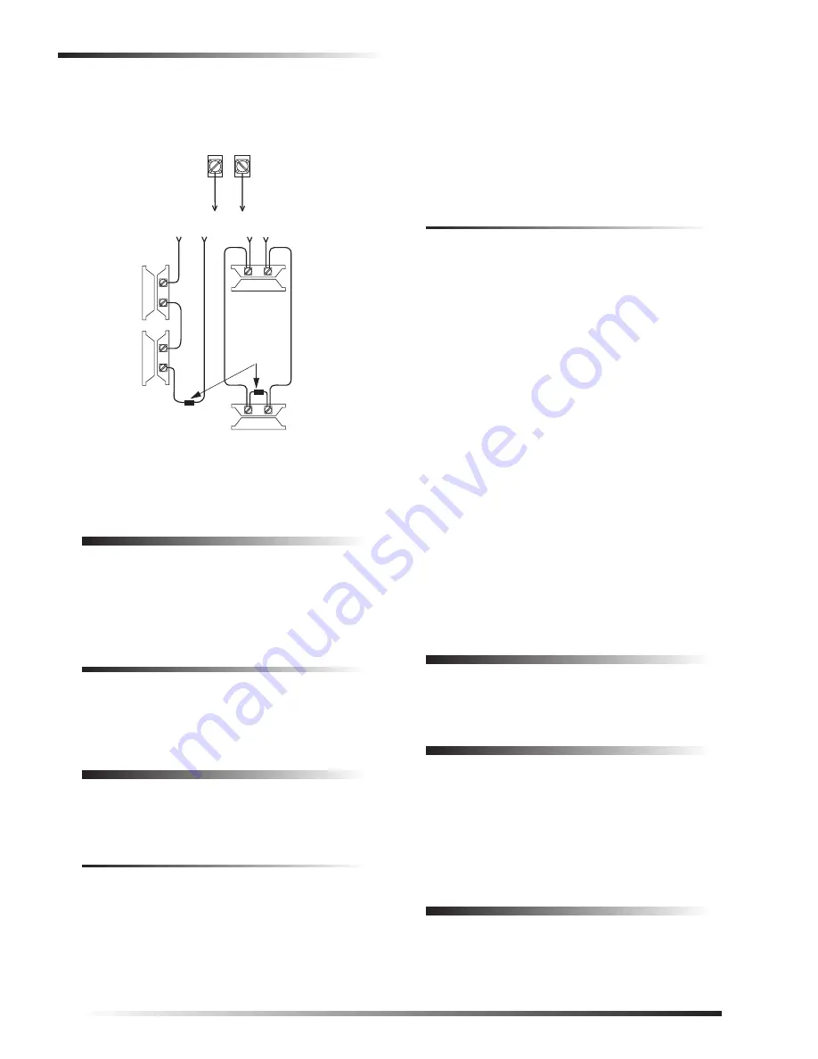
Figure 9. Wiring the RF Transceiver Hardwire Zone
Setting the Module Device Address
Each bus module connected to the panel SuperBus must
have a unique (different) device address number set for cor-
rect communication. SuperBus 2000 compatible panels
such as Advent set the bus address automatically.
Setting the Device Address for
Advent
Panels
The Advent SuperBus 2000 compatible panel automatically
sets the module bus address when the module is added
(learned) into panel memory.
Power Up and Bus Communication
Use the following procedures for powering up the system
and verifying bus communications for both new and exist-
ing installations.
New Installations
1.
Verify that all wiring at the panel and the transceiver is
correct.
2.
Connect the panel backup battery and the AC power
transformer. Alphanumeric touchpad displays should
come on.
3.
Verify that the transceiver module green power LED is
on and the red bus LED flashes to indicate successful
communication with the panel.
Ìi
If the transceiver power LED is not on or the red bus
LED does not flash, unplug the panel AC power trans-
former, disconnect the backup battery, and see “Trou-
bleshooting.”
Existing Installations
1.
Verify that all wiring at the panel and the transceiver is
correct.
2.
Connect the panel backup battery and the AC power
transformer. Alphanumeric touchpad displays should
come on.
3.
Press 8 to select System Menu.
4.
Press 0 to select Enter Program Mode.
5.
Enter the install code (defaults to 0123).
6.
Enter Item Number 48001 to add SuperBus devices.
All installed devices are automatically added (learned)
into panel memory when Devices Added is indicated.
7.
Press * twice to return to the normal mode of operation
and refer to the “Testing Sensors/Inputs” section of the
panel Installation Instructions for testing module oper-
ation.
8.
Verify that the transceiver module green power LED is
on and the red bus LED flashes to indicate successful
communication with the panel.
Ìi
If the transceiver power LED is not on or the red bus
LED does not flash, unplug the panel AC power trans-
former, disconnect the backup battery, and see “Trou-
bleshooting.”
Wireless Sensor Programming
Refer to the panel Installation Instructions for adding
(learning) wireless devices into panel memory.
Testing
Verify that the module red bus LED flickers when wireless
devices are activated. Verify that the panel recognizes wire-
less device and hardwire zone actuation (if used).
For complete testing procedures, refer to the panel Installa-
tion Instructions.
Troubleshooting
Module green power LED stays off.
1.
Check for incorrect wiring connections and for panel
power.
ZONE
1
ZONE
COM
UL-LISTED
NORMALLY
OPEN
(N/O) CONTACTS
IN PARALLEL
2.0K OHM
EOL RESISTOR
49-467
(LOCATE AT
LAST
DEVICE)
UL-LISTED
NORMALLY
CLOSED (N/C)
CONTACTS
IN SERIES
< OR >
SUPERBUS COMMERCIAL
RF TRANSCEIVER
MODULE


