


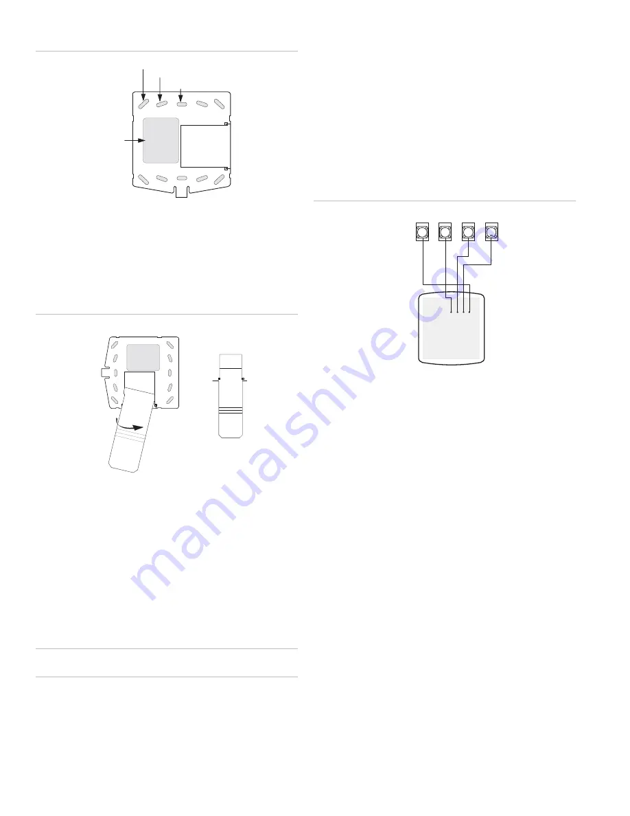
Figure 2: Mounting holes
Wall Mounting Holes (4)
Dual-Gang Mounting Holes (4)
Single-Gang Mounting Holes (4)
Wire Access Area
4. Looking at the back side of the mounting plate, turn it so
the tab is on the left and position the Quick Guide slide-
out card into the slots on back of the mounting plate (see
A in Figure 3 below). Make sure the card is unfolded and
the “Zones” section is facing you.
5. Slide the card in the direction of the arrow in Figure 3
below (A) until it snaps into the position shown in (B).
Figure 3: Inserting the Quick Guide Slide-Out card
Swing card over in
Direction of Arrow
Until Card Snaps into Place
A
B
6. Position the mounting plate in its normal mounting position
(tab at the bottom) and fold the card toward you at all
three scored lines. The “Zones” section should be facing
you and the folds should create a tab to slide the card in
and out.
7. Align the mounting plate wall-mount holes with the wall
anchors and secure the back-plate to the wall using the
screws provided.
OR If installing the back-plate on an electrical gang box,
line up the appropriate gang box holes on the mounting
plate with the gang box holes and secure the back-plate to
the gang box using the screws provided.
Caution:
Do not over tighten screws or the back plate may
bend and prevent the touchpad from mounting properly.
8. For wall-mounted installations, cut a hole in the wall in the
wire access area of the mounting plate to pull your cable
through for wiring.
Wiring
Wiring consists of connecting the touchpad to the panel
terminals.
1. Disconnect the panel transformer and backup battery.
2. Run a 4-conductor, 18- to 22-gauge wire from the panel to
the touchpad location.
3. Splice the 4-conductor cable wires to the red, black,
green, and white wires located on the back of the
touchpad.
4. Connect the touchpad wiring to the panel terminals as
shown in Figure 4 below.
Figure 4: Wiring touchpad to panel terminals
3
4
5
6
BACK OF
T
OUCHPAD
GND/
BLACK
+12V/
R
ED
N
E
E
R
G/
A
S
U
B
BUS
B/
W
H
IT
E
+12V
A
B
GND
BUS
Attaching the Touchpad to the Mounting Plate
Align the four slots on the touchpad with the four tabs on the
mounting plate and slide the keypad down until you hear the
latch on the mounting plate click into place.
Power Up
After making all wiring connections from the touchpad to the
panel, you are ready to power up the panel. Upon power up,
the panel scans the bus for connected devices and
automatically learns the unit number of each bus device.
Note
: If you plan on installing systems with no alphanumeric
touchpads, it is recommended that you keep an alphanumeric
touchpad with you, specifically for programming. This touchpad
can be quickly connected and disconnected from the header
pins on the lower portion of the panel circuit board, as
described later in this document.
To power up the panel and verify bus communication:
1. Verify that all wiring between the panel and touchpad is
correct.
Note
: If the touchpad does not display the date and time,
see “Troubleshooting” on page 4.
2. Connect the panel battery and plug in the panel
transformer. Alphanumeric touchpads should show a date
and time display.
Connecting the touchpad for system programming only
For installations that don’t include an alphanumeric touchpad
as a permanent part of the system, you can connect one for
2
SuperBus 2000 2X16 LCD Alphanumeric Touchpad Installation Instructions