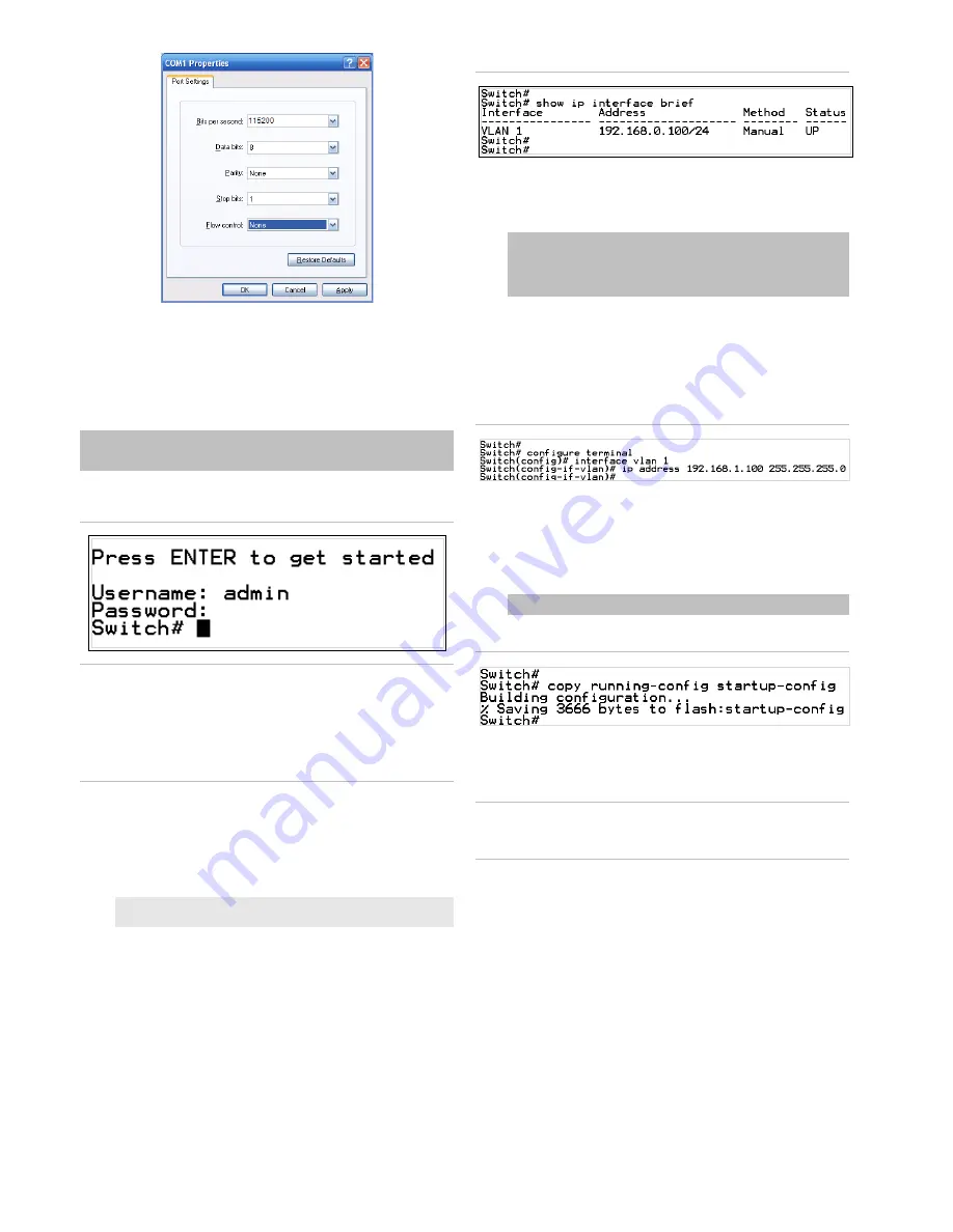
3. Log in to the console.
After
the terminal has
been
connected to the device, power on the
managed
switch
.
T
he terminal display
s
“running testing procedures”
.
When the following dialog box in Figure
3
below
appears,
type
the
factory default user
name "
admin
" and password
“
admin
”.
User name:
admin
Password:
admin
Figure 3: Console login screen
Note:
1.
For security purposes, change and memorize the new
password after this first setup.
2.
Only command
s
in lowercase letter
s are accepted in the
console interface.
Configuring the IP address
The
managed switch
is shipped with
the
default
IP address
shown below:
IP
Address:
192.168.0.100
Subnet Mask:
255.255.255.0
To check the current IP address or modify a new IP address
for the
managed
switch, use the following procedure
s:
Display of the current IP Address
1. At the “#” prompt,
type
“
show
ip interface brief
”.
2. The screen displa
ys the current IP address.
Figure 4: IP information screen
Configuration of the IP address
3. At the “#” prompt,
type
the following command and press
Enter
as show
n
in Figure 5
.
Switch#
configure terminal
Switch(config)#
interface vlan 1
Switch(config-if-vlan)#
ip address 192.168.1.100
255.255.255.0
The previous command would apply the follow
ing settings
for the
managed
switch
.
IP
Address:
192.168.1.100
Subn
et
Mask: 255.255.255.0
Figure 5: Configuring the IP address screen
4
.
Repeat step 1 to check if the IP addres
s has changed.
Store the current switch configuration
5
. At the “
#
” prompt,
type
the following command and press
Enter.
# copy running
-
config startup
-
config
Figure 6: Saving current configuration command screen
If the IP is successfully configured, the
managed
switch
applies
the new IP address setting immediately.
Access the
web
interface of
the managed
switch through the new IP address
.
Note
: If unfamiliar with
the console command or the related
parameter,
type
“help” in the console to
obtain the H
elp
description.
Starting web management
The
section describes
how to start
up the
web m
anagement
function for
the managed
switch
. Note that the managed
switch
is configured through an Ethernet connection
. En
sure
that the
manager
computer is
set to the same
IP subnet address
.
For
example, if the default IP address of the managed switch
is
192.168.
0.100, then the manager
compu
ter
should be set
to
192.168.
0
.x
(where x is a number between 1 and 254, except
100), and the default subnet mask is 255.255.255.0.
2 /
4
P/N 1073387-EN
• REV
A
• ISS
06FEB18


