background image


P/N 1073550-EN • REV B • ISS 01FEB19 


3 / 6 

Wall-mount plate mounting 

To install the industrial gigabit Ethernet switch on the wall, 
follow the steps below. 

1.  Remove the DIN-rail from the industrial gigabit Ethernet 

switch. Loosen the screws to remove the DIN-rail. 

2.  Place the wall-mount plate on the rear panel of the 

industrial gigabit Ethernet switch. 


3.  Use the screws to screw the wall-mount plate on the 

industrial gigabit Ethernet switch. 


4.  Use the hook holes at the corners of the wall-mount plate 

to hang the industrial gigabit Ethernet switch on the wall.


5.  To remove the wall-mount plate, reverse the steps above. 

Terminal setup 

To configure the system, connect a serial cable to a COM port 
on a PC or notebook computer and to RJ45 type serial 
(console) port of the industrial managed switch. The console 
port of the industrial managed switch is DCE already so that 
you can connect the console port directly through a computer 
without the need of null modem. 

Figure 3: Console connectivity 


A terminal program is required to make the software connected 
to the industrial managed switch. Windows' Hyper Terminal 
program may be a good choice. The Hyper Terminal can be 
accessed from the 

Start

 menu.  

1.  Click 

Start

 > 

Programs

 > 

Accessories

 > 

Hyper 

Terminal

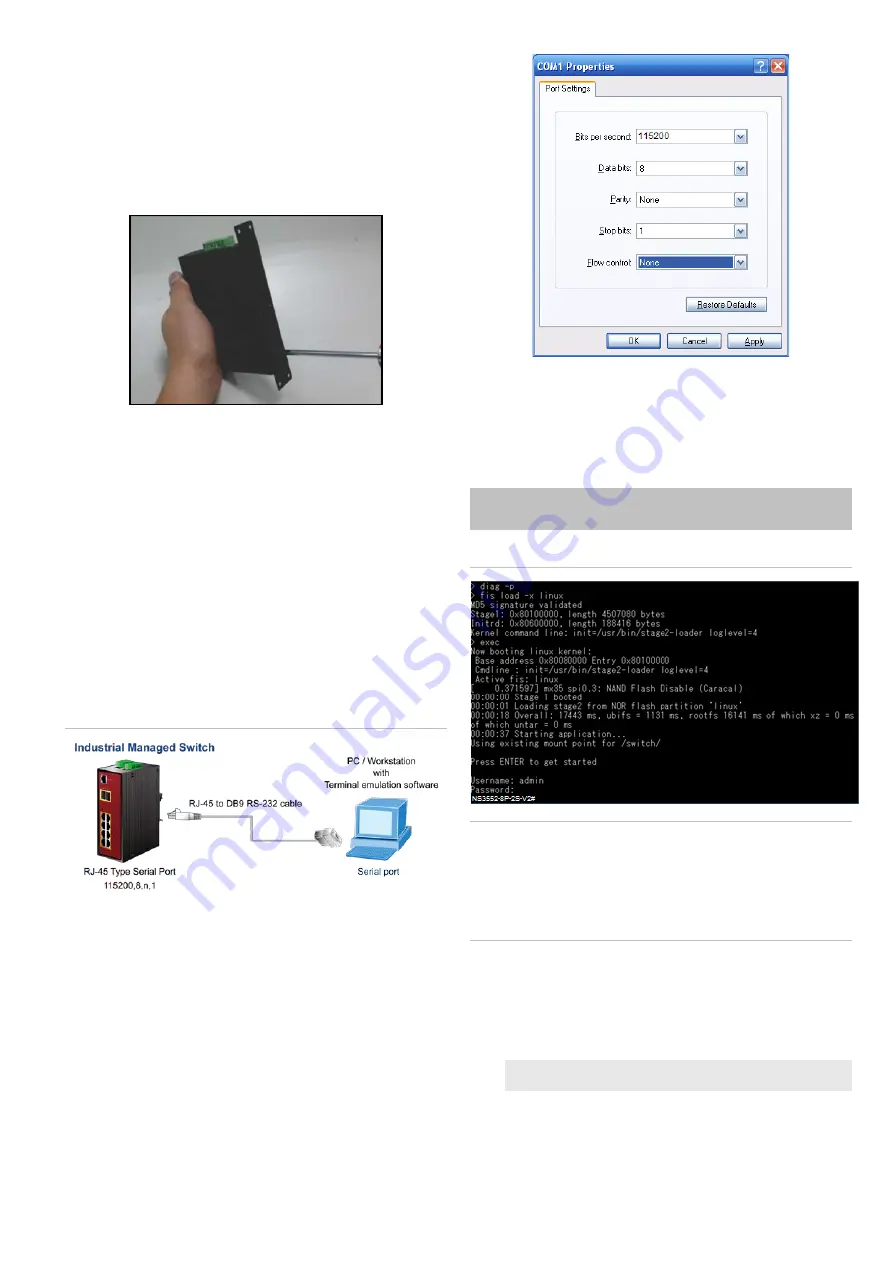
2.  When the following screen appears, ensure that the COM 

port is configured as shown below. Click 

OK

 when finished 

with configuration. 


3.  Log in to the console. After the terminal has been 

connected to the device, power on the industrial managed 
switch. The terminal displays “running testing procedures”.


When the following dialog box in Figure 4 below appears, 
type the factory default user name "

admin

" and password 

admin

”.  

User name: 

admin


Password: 

admin


Figure 4: Console login screen 


Note: 


1.  For security purposes, change and memorize the new 

password after this first setup. 

2.  Only commands in lowercase letters are accepted in the 

console interface. 

Configuring the IP address 

The industrial managed switch is shipped with the default IP 
address shown below:  


IP Address: 

192.168.0.100 

Subnet Mask:

 255.255.255.0


To check the current IP address or modify a new IP address 
for the industrial managed switch, use the following 
procedures: 

Summary of Contents for NS3552-8P-2S-V2

Page 1: ...anagement purposes The following equipment is necessary for further management Workstations running Windows XP 2003 Vista 7 8 2008 10 MAC OS X or later Linux UNIX or other platforms are compatible with TCP IP protocols Workstations are installed with Ethernet NIC Network Interface Card Serial port connection Terminal The above workstations come with a COM Port DB9 or USB to RS 232 converter The ab...

Page 2: ...not mount the switch horizontally as this does not allow air to flow up into the device and will result in damage to the switch Do not tie DC1 to DC2 DC2 is for secondary power redundancy Do not plug DC power into the device while the AC power cord is plugged in This is not a hot swappable switch Hot swapping this device will result in damage DIN rail mounting installation To replace the wall moun...

Page 3: ...ivity A terminal program is required to make the software connected to the industrial managed switch Windows Hyper Terminal program may be a good choice The Hyper Terminal can be accessed from the Start menu 1 Click Start Programs Accessories Hyper Terminal 2 When the following screen appears ensure that the COM port is configured as shown below Click OK when finished with configuration 3 Log in t...

Page 4: ...ch through the new IP address Note If unfamiliar with the console command or the related parameter type help in the console to obtain the Help description Starting web management The section describes how to start up the web management function for the industrial managed switch Note that the industrial managed switch is configured through an Ethernet connection Ensure that the manager computer is ...

Page 5: ...g command After doing this the running configuration sequence becomes the startup configuration file i e the saved configuration To save all applied changes and set the current configuration as a startup configuration the startup configuration file is loaded automatically across a system reboot 1 Click System Save Startup Config 2 Click the Save Configuration button Resetting the switch to default...

Page 6: ...286 8889 E techsupport interlogix com W www interlogix com support Latin America T 1 561 998 6114 E latam interlogix com Europe Middle East and Africa W Select Contact Us at www firesecurityproducts com Australia E security tech support interlogix com au W www utcfs com au support ...

Reviews: