background image

4 / 14 


P/N 466-5519 • REV 0.01 • 24MAY19 

Mount the thermostat 

x

24VAC Powered Thermostat: 

If the thermostat is 

24VAC powered (24VAC common “C” wire is 

connected), 

DO NOT INSTALL BATTERIES!

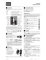
Figure 4: 

24VAC Powered Thermostat 

1.  Install the thermostat on to the base. 

2.  Turn on power to the HVAC system/thermostat. 

x

Battery Powered Thermostat:

 If the thermostat is 

battery powered (NO 24VAC common “C” wire 

connected), install 4 NEW Alkaline AA batteries into the 

back of the thermostat. 

Figure 5: 

Battery Powered Thermostat 

1.  Install the thermostat on to the base. 

2.  Turn on power to the HVAC system/thermostat. 

Summary of Contents for IS-ZW-TSTAT-500

Page 1: ... Inc Interlogix is part of UTC Climate Controls Security a unit of United Technologies Corporation All rights reserved Safety Information WARNING CHOKING HAZARD The product accessory bag contains items that could be choking hazards Please keep away from small children AVERTISSEMENT Le sachet de produits accessoires contient des éléments qui pourrait présenter un danger d étouffement Veuillez garde...

Page 2: ...he wires attached to the terminals with the wiring labels included 3 Use the terminal labels and not the wiring color to mark the wires 4 Remove the old thermostat base CAUTION Don t let the wires slip into the wall Figure 1 Thermostat Wiring Note The C wire 24V common may not be present If C wire is not present the thermostat must be powered by batteries ATTENTION If the C wire is present you can...

Page 3: ...d cooling systems with separate 24VAC transformers For those systems there will be a separate R wire for the heating system RH and cooling system transformers RC To connect separate transformer systems FIRST REMOVE THE SUPPLIED RH RC JUMPER Then connect the heating R wire to the RH terminal and the cooling R wire to the RC terminal on the thermostat Heat Pump HVAC Systems Wiring Figure 3 Single st...

Page 4: ...Powered Thermostat 1 Install the thermostat on to the base 2 Turn on power to the HVAC system thermostat x Battery Powered Thermostat If the thermostat is battery powered NO 24VAC common C wire connected install 4 NEW Alkaline AA batteries into the back of the thermostat Figure 5 Battery Powered Thermostat 1 Install the thermostat on to the base 2 Turn on power to the HVAC system thermostat ...

Page 5: ...pical gas furnace fan is controlled by the furnace x Set to ELECTRIC for electric heat fan on with heat call For Two Stage Heat Cool Systems Go to ADVANCED SYSTEMS SETTINGS menu From the Setup menu screen press and hold the Fan button and Down arrow buttons for 5 seconds Use the Down arrow button to select the following x 2nd Stage Heat Enable Enable second stage heating output If a single stage h...

Page 6: ... and holding the FAN button for 5 seconds 2 Press the down arrow to select the SYSTEM menu and press Select Set the following x System Type Set to HEAT PUMP x Change Over For changeover with cooling systems Orange wire set to WITH COOL most common and default setting For changeover with heating systems Brown wire set to WITH HEAT You must configure the thermostat s changeover valve setting to work...

Page 7: ...AC system the System setup does not need to be changed Installation is complete For thermostats installed on a Heat Pump HVAC system or any HVAC configuration other than the preset settings the System settings need to be changed in the SYSTEM setup menu to match the HVAC system Changing the HVAC System Setup To change the thermostats HVAC system settings first select the Menu Screen and then selec...

Page 8: ...system x Set the Change Over setting accordingly CAUTION These are typical wiring colors connections and may differ x If heating comes on when cooling is expected or vice versa change the Change Over Type to the opposite setting Advanced System Settings Menu The Advanced System Settings Menu provides for addition system setup options These settings can affect system operation and should only be ch...

Page 9: ...nued Setpoint Push x Attempts to lower the cooling setpoint below the heating setpoint will PUSH the heating setpoint down to maintain the heat cool delta separation x Attempts to set the heating setpoint above the cooling setpoint will PUSH the cooling setpoint up to maintain the setpoint heat cool delta separation Heating Stage 1 On Threshold Range 1 to 6 Default 1 Sets the delta from setpoint t...

Page 10: ...ostat Backlight Display IS ZW TSTAT 500 Table 2 System Operation Modes Icon Description System is ON and heating If flashing minimum run time MRT is active System is ON and cooling If flashing minimum run time MRT is active LLOW BATTY Battery indicator Display lock indicator Z Wave network indicator Stage Indicators x 1 Stage 1 heating or cooling is ON x 2 Stage 2 heating or cooling is ON x 3 Stag...

Page 11: ...the Up or Down arrow buttons The screen will switch to the setpoint change screen as above and show the current setpoint of the current heating or cooling mode Adjust setpoint temperature up or down with the arrow buttons Note When in the Setpoint Change screen pressing the MODE button will switch the setpoint being displayed between the Heat and Cool setpoints x Setpoint Push The cooling setpoint...

Page 12: ...ired temperature displayed x Humidity Sensor Calibration Change the humidity calibration by 7 Use the Up Down arrow buttons to change to the desired humidity displayed x Status Line display Select Setpoints or Humidity to be displayed on the upper status line System Menu x System type Select the system type Standard or Heat Pump Fan type standard systems only x Select fan type Gas typical default ...

Page 13: ...d as an always listening device and can act as a router node in the Z Wave network CAUTION Once installed in a Z Wave network if you change how the thermostat is powered from batteries to 24VAC or vice versa you must remove and re enroll the thermostat in the Z Wave network for it to work correctly Adding the thermostat to a Z Wave network 3 Follow the instructions provided with your system for en...

Page 14: ...the user is encouraged to try to correct the interference by one or more of the following measures x Reorient or relocate the receiving antenna x Increase the separation between the equipment and receiver x Connect the equipment into an outlet on a circuit different from that to which the receiver is connected x Consult the dealer or an experienced radio TV technician for help Any changes or modif...

Reviews: