


2. Open the panel cover.
3. Release the top chassis latch from the back plastic with a
small screwdriver (twist the screwdriver).
4. Flip the front cover down until the back plastic is exposed.
5. Disconnect the backup battery.
6. With the Ethernet connector on the module facing the
hinge of the panel, align the holes on the left side of the
module with the plastic pins on the left side of the panel
back plastic.
7. Secure the module to the screw posts on the panel
through the holes on the right of the module using the
included mounting screws.
To wire the Ethernet Interface module to a Simon
panel:
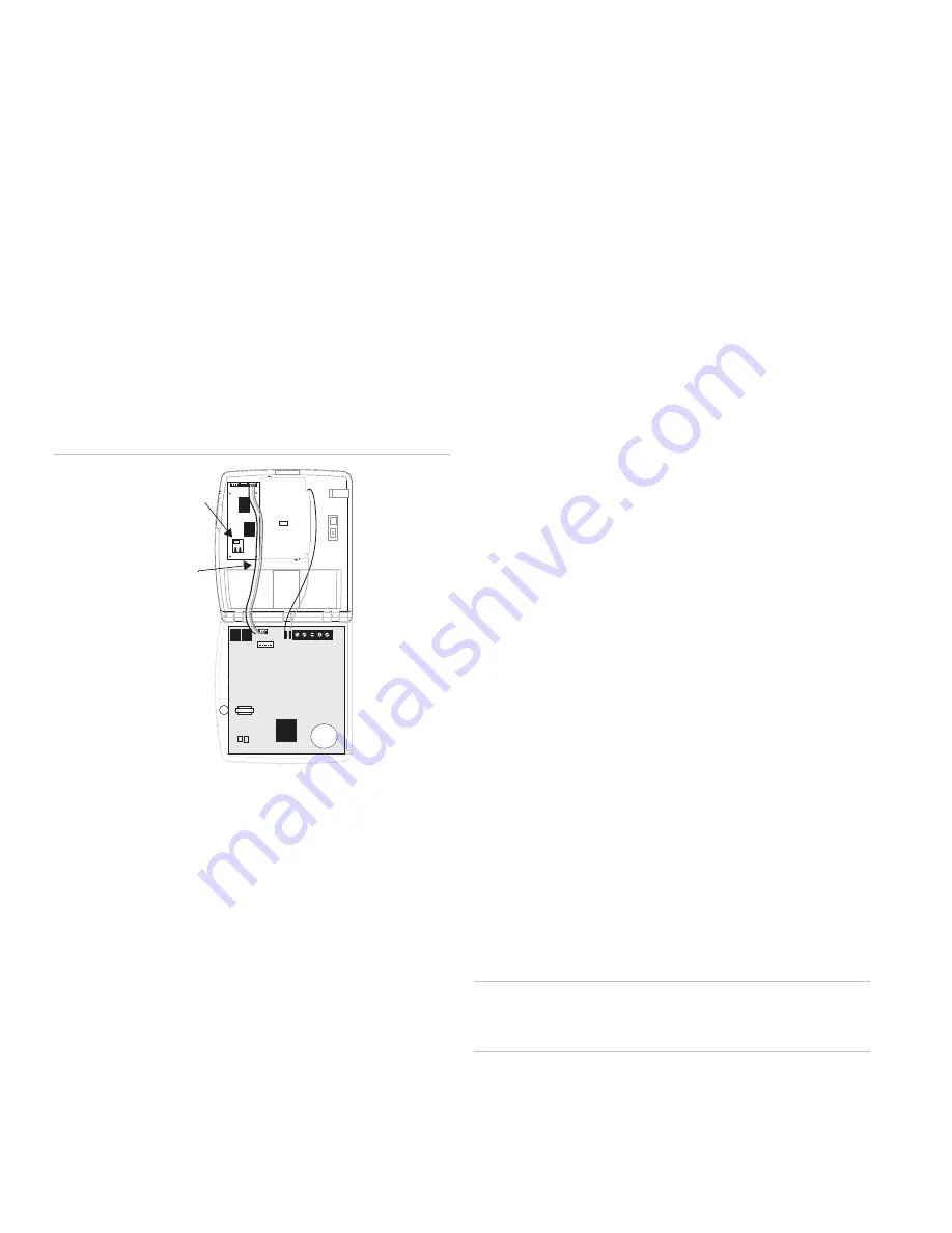
Figure 2: Wiring the Ethernet Interface Module
Wiring
Harness
Ethernet
Connector
1. Connect one end of the included wiring harness to the
right 4 pins on the top of the module. The red wire on the
harness should be to the right.
2. Connect the other end of the wiring harness to the pins
located just to the right of the phone jacks on the panel.
The red wire on the harness should be to the right.
3. Connect one end of the Category 5e Ethernet cable to the
Ethernet connector on the bottom left of the module.
4. Connect the other end of the Ethernet cable to an
available Ethernet port on your cable or DSL modem, hub,
switch or router (see Figure 3 on page 3).
5. Make any other wiring or phone connections at this time.
See the
Simon Installation Instructions
for necessary
connections.
6. Reconnect the backup battery.
7. Close the panel cover.
8. Apply AC power.
Connection
Connecting the Ethernet Interface Module to a
Network
There are several possible network configurations the Simon-
Ethernet Interface module System may take. The following are
guidelines for connecting the system to a network.
•
The module must be connected to an available 10-Base-T
or 10/100-Base-T Ethernet Port that leads to the Internet.
(The port cannot be labeled “WAN” or “Uplink”.)
•
The module is not compatible with USB.
•
If Remote Option 5 is On there must be a DHCP Server on
the local network. (A DHCP Server is usually built into
routers.) If Remote Option 5 is off, Remote Option 7 must
be programmed with a legal Static IP Address.
For UL Listed Systems
•
The network connection must be always on and not
require the use of the public switched telephone network
to make a “dial up” connection.
•
All devices between the Ethernet Interface and the
transmission line (ethernet port or “hub”, router, cable
modem, etc.) must be UL listed models and not receive
power from a switched outlet.
•
Supervision signals between the panel and the
supervising station receiver (central station) must be
managed by the central station and not an intermediary
network agent, device or service.
•
Lost communication between the system and the reporting
station will be indicated at the reporting station within 90
seconds.
•
The communication path between the panel and the
receiver can be either DACT or internet. One is not a
backup for the other.
Caution:
If connecting devices (“hub”, router, cable modem)
do not have battery backup. The system will lose
communication with the reporting station if AC power is lost.
2
Ethernet Interface Installation Instructions


