


P/N 466-1452
• REV E • ISS 16OCT18
5 / 10
1. Loosen the inside terminals of the left and right antenna
terminal blocks.
2. Insert an antenna end into each inside terminal.
3. Tighten the terminal screws.
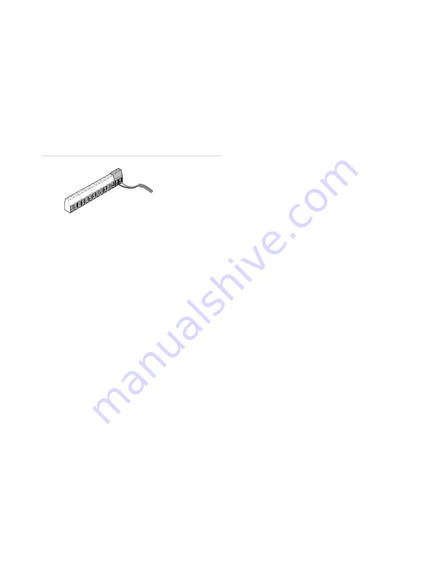
Connecting power to the receiver
To connect power to the receiver, do the following:
1. Turn off or remove power from the panel and disconnect
the battery.
2. Wire receiver terminals (GND) and (+12V) to a non-
switched 12 V supply output on the control panel. Make
sure you observe the correct polarity (see Figure 8).
Figure 8: Connect power to the receiver
3. Turn on or apply power to the panel.
Zone planning
Before programming, write down how you plan to use the
transmitters with each zone.
The following guidelines describe the receiver zone
capabilities. Use these guidelines to complete Table 2 and
record the wireless devices used for each zone.
Keychain touchpads
The receiver can learn up to 45 keychain touchpads. The
following describes the keychain touchpad button functions.
Suggested applications include panic button, momentary or
maintained (toggle on/off) control panel activation for
arming/disarming, or momentary activation for a garage door
opener.
Note:
All keychain touchpads learned into the receiver
control the same zone outputs. For example, if keychain
touchpad #1 is learned into zone 1 and keychain touchpad
#2 is learned into zone 2, both keychain touchpads control
both zones.
Zone 1. Lock + unlock
This simultaneous keypress can be learned only into zone 1
and still allows you to learn two additional sensors into zone
1. When learned, this keypress causes a momentary alarm
on zone 1.
Note:
Both panic button transmitters and this keypress can
be learned into zone 1 together; however, the total number of
panic buttons and keychain touchpads learned into zone 1
cannot exceed 45. For zones 2 through 6, keychain
touchpads and other sensors cannot be learned into the
same zone.
Zone 2 (lock or unlock)
When learned into zone 2, both of these key presses work
together to provide a maintained (toggle) output response
(only one of these buttons needs to be learned for both to
work).
Typically, this output would be used for a maintained
keyswitch on the control panel for arming/disarming (refer to
your control panel documentation for this application).
Zone 3 (lights)
You can only learn this keypress into zone 3. When learned,
pressing this button switches the zone 3 output. The output
can be configured to switch momentarily (default) or
maintained (toggle on/off for each press). See
“Keychain
touchpad zone output responses
” en page 7.
Zone 4 (star)
You can only learn this keypress into zone 4. When learned,
pressing this button switches the zone 4 output. The output
can be configured to switch momentarily (default) or
maintained (toggle).
See “Keychain touchpad zone output
responses
” en page 7.
Zone 5 (lock)
You can only learn this keypress into zone 2 (as detailed
above) or zone 5. When learned into zone 5, pressing this
button switches the zone 5 output. The output can be
configured to switch momentarily (default) or maintained
(toggle). See
“Keychain touchpad zone output responses” on
page 7.
Zone 6 (unlock)
You can learn this keypress into zone 2 (as detailed above)
or zone 6. When learned into zone 6, pressing this button
switches the zone 6 output. The output can be configured to
switch momentarily (default) or maintained (toggle). See
“Keychain touchpad zone output responses” on page 7.
Tamper and trouble conditions
Zone 7
Jam detection is set to automatically monitor for radio signals
that can jam the receiver. However, once a transmitter is
learned into zone 7, the RF jam detection is disabled.
Zone 8
Cover/antenna tamper is set to automatically monitor cover
and antenna removal. However, once a transmitter is learned
into zone 8, the cover/antenna tamper is disabled.
Low battery
Receiver terminal B activates whenever the receiver gets a
signal from a transmitter with a low battery. To monitor for
low transmitter battery conditions, connect the receiver B
output to a control panel zone input.
To panel’s 12V supply