Page 6
SWITCH DEFINITIONS
Mode Selection Switch (S1)
S1 is used to cycle through the various programmable functions of the 9834. The
sequence is as follows. The designators, in ( ), identify text that will be displayed.
The settable values are shown in { }
Factory Default Settings
Full Scale CAL Switch Disabled (CAL Off) or Enabled (CAL On)
(CAL Off)
Filter Window Value (bAnd) {001 to 999}
{010}
Filter Value (FILtEr) {00 to 99}
{95}
Decimal Point (dP) {x.xxxx, xx.xxx, xxx.xx, xxxx.x, xxxxx}
{xxxxx}
Calibration Number (CAL) {00001 to +99999}
{10000}
Full Scale Number (FS) {00001 to +99999}
{10000}
Setpoint 1 to Monitor (SP -) {Instantaneous, Peak, Valley, Peak-Valley}
{Instantaneous}
Setpoint 1 to be (SP HI) {High Setpoint} or (SP LO) {Low Setpoint}
{High Setpoint}
Set Setpoint 1 Value (Set SP) {00000 to +99999}
{99999}
Setpoint 2 to Monitor (SP -) {Instantaneous, Peak, Valley, Peak-Valley}
{Instantaneous}
Setpoint 2 to be (SP HI) {High Setpoint} or (SP LO) {Low Setpoint}
{High Setpoint}
Set Setpoint 2 Value (Set SP) {00000 to +99999}
{99999}
Setpoint 3 to Monitor (SP -) {Instantaneous, Peak, Valley, Peak-Valley}
{Instantaneous}
Setpoint 3 to be (SP HI) {High Setpoint} or (SP LO) {Low Setpoint}
{High Setpoint}
Set Setpoint 3 Value (Set SP) {00000 to +99999}
{99999}
Setpoint 4 to Monitor (SP -) {Instantaneous, Peak, Valley, Peak-Valley}
{Instantaneous}
Setpoint 4 to be (SP HI) {High Setpoint} or (SP LO) {Low Setpoint}
{High Setpoint}
Set Setpoint 4 Value (Set SP) {00000 to +99999}
{99999}
Hysteresis for Low Setpoints (HL) {000 to 200}
{000}
Hysteresis for High Setpoints (HH) {000 to 200}
{000}
Depress Mode Again to Exit (AgAIn)
While in the Mode Selection sequence, the indicator is no longer monitoring the
input signal. To exit, depress S1, once, after the Decimal Point selection is
completed.
Decrement or Tare Switch (S2)
This switch serves two functions, depending on the present status of S1. If the meter
is in the Mode Selection sequence, this switch decrements the flashing digit.
If the meter is in its normal operating mode, S2 becomes the TARE switch.
Depressing S2 will automatically zero the readout, illuminate the TARE LED and
zero the analog output. Depressing and holding S2 depressed for approximately
3 seconds will UNTARE the readout and extinquish the TARE LED. TARING is
accomplished by storing the reading prior to TARING and subtracting this value from
all subsequent readings.
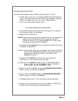
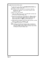
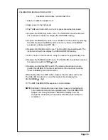
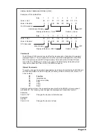
SWITCH AND FUNCTION DEFINITIONS
MODE
TARE
CAL
CAL
TARE
SP1
SP2
SP1
SP2
Model 9834
DISP
RESET
REF
PK
VAL
S1 S2 S3 S4
S5
S7
S6


