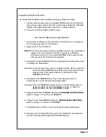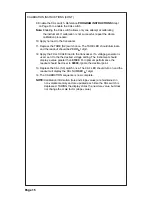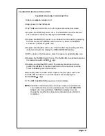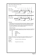
CALIBRATION INSTRUCTIONS
The Interface Model 9834 can be calibrated using (2) different methods.
1. The first method uses actual or simulated ZERO and FULL SCALE (FS)
inputs. Actual inputs may come from a transducer loaded with calibrated
weights. Simulated inputs may come from a voltage calibrator.
2. The second method utilizes an REF switch.
ACTUAL OR SIMULATED LOAD METHOD
1. Connect the transducer to the instrument using Figure 3 as a reference.
Do not apply any load to the transducer.
2. Apply power to the instrument.
NOTE:
If the instrument was previously calibrated and no new calibration is
required, do not proceed any further. All previous calibration
information is stored in non-volatile EEPROM and is ready for use
when power to the instrument is reapplied.
3. Calculate the CAL NUMBER (CAL) by verifying the load that will be used
to calibrate the Model 9834.
Example: If a 500 pound load is used to calibrate and the desired readout is
500.0, the CAL NUMBER will be 5000. The decimal point can be
selected later. If the desired readout is 500 then the CAL
NUMBER will be 500.
4. Calculate the FS NUMBER (FS). This is the value used, by the
microprocessor, to set the full scale analog output.
Example: If the CAL NUMBER is 5000, but the +10VDC analog output is
desired at 7500, set the FS NUMBER to 7500. If +10VDC is
desired at 5000, set the FS NUMBER to 5000.
5. Program in the CAL NUMBER. Reference
PROGRAM INSTRUCTIONS,
Step 5 on Page 11 to set the CAL NUMBER.
6. Program in the FS NUMBER. Reference
PROGRAM INSTRUCTIONS
,
Step 6 on Page 11 to set the FS NUMBER.
7. The TARE and CAL LED's on the front panel should be illuminated.
8. Depress and hold the TARE (S2) switch. The TARE LED will extinquish
and the instrument will display the UNTARED reading.
Page 14


