


PROFESSIONAL POWER AMPLIFIER
7
V2-5000
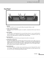
Rear Panel
Rear Panel
1. AC CORD
Connect this product to an appropriate AC main power source.
2. OUTPUT CONNECTORS
4 Pole speaker sockets are provided. Bridged mono operation requires a different method of connecting the
speaker cables than stereo operation. Be sure that the amplifier is in the correct mode before connecting the
speaker load. Please refer to the output connection drawings.
3. MODE SELECTOR SWITCH
Move this switch to select the stereo, parallel or bridged mono position as needed for the application. The
stereo mode is most common. Channel A input provides signal through the amplifier to the channel A
output. The channel B input provides signal through the amplifier the channel B output. The parallel mode
uses the channel A input provides signal through the amplifier to both the channel A and channel B outputs.
No input will be supplied to channel B in the Parallel mode. The bridge mono mode combines both channels
to create one larger mono channel. Input signal applied to channel A will provide signal through the
amplifier to the positive terminals of channel A and channel B. Do not connect any signal to the channel B
input or any loads to the negative outputs.
4. VOLTAGE GAIN SELECTOR SWITCH
You can drive the amplifier with different gain structure, 1.4V, 32dB or 26dB, which is possible the amplifier
to accept a various input level.
5. 3-Pin Euroblock Input Connectors
These connectors are used for balanced or unbalanced input signals. For parallel mode or bridged mode,
use INPUT 1 only.
PUSH
PUSH
INPUT A
INPUT B
CH A CH B
CH B
CHANNEL
B
CHANNEL
A


