STEREO TUNER
2
TU-6200
Installation
Unpacking
Unpacking
Although your TU-6200 is neither complicated nor difficult to operate, we recommend you take a few minutes
to read this brief manual and familiarize yourself with the important information regarding product features,
setup and operation.
As with most electronic devices, we strongly recommend you to retain the original packaging. In the unlikely
event the product must be returned for servicing, the original packaging (or reasonable equivalent) is required.
Installation
Environment
Never place this product in an environment which could alter its performance or reduce its service life. Such
environments usually include high levels of heat, dust, moisture, and vibration.
IMPORTANT SAFETY INSTRUCTIONS
1. Read these instructions.
2. Keep these instructions.
3. Heed all warnings.
4. Follow all instructions.
5. Do not use this apparatus near water.
6. Clean only with dry cloth.
7. Do not block any ventilation openings. Install in accordance with the manufacturer’s instructions.
8. Do not install near any heat sources such as radiators, heat registers, stoves, or other apparatus (including
amplifiers) that produce heat.
9. Do not defeat the safety purpose of the polarized or grounding-type plug. A polarized plug has two blades
with one wider than the other. A grounding type plug has two blades and a third grounding prong. The wide
blade or the third prong are provided for your safety. If the provided plug does not fit into your outlet, consult
an electrician for replacement of the obsolete outlet.
10. Protect the power cord from being walked on or pinched particularly at plugs, convenience receptacles, and
the point where they exit from the apparatus.
11. Only use attachments/accessories specified by the manufacturer.
12. Use only with the cart, stand, tripod, bracket, or table specified by the manufacturer, or sold with the apparatus.
When a cart is used, use caution when moving the cart/apparatus combination to avoid injury from tip-over.
13. Unplug this apparatus during lightning storms or when unused for long periods of time.
14. Refer all servicing to qualified service personnel. Servicing is required when the apparatus has been
damaged in any way, such as power-supply cord or plug is damaged, liquid has
been spilled or objects have fallen into the apparatus, the apparatus has been
exposed to rain or moisture, does not operate normally, or has been dropped.
S3125A
Summary of Contents for TU-6200
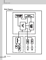
Page 10: ...STEREO TUNER 8 TU 6200 Block Diagram Block Diagram...
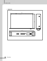
Page 12: ...STEREO TUNER 10 TU 6200 DIMENSIONS 440 482 88 280...
Page 14: ...NOTE...
Page 15: ...NOTE...


