1485 Jacobs Rd.
Deland, FL 32724
386.738.7307
P/N 53-00571-100 Rev. B 032619
www.intellitec.com
Intellitec
SERVICE MANUAL
MONOPLEX SPEAKER SWITCH
HOW IT WORKS
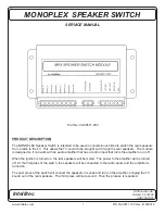
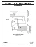
The MONOPLEX Speaker Switch provides a means of switching the two rear speakers to allow switching
between the four radio inputs and two TV inputs. The actual switching is done with relays. These relays
are controlled by the control electronics to provide the functions of the unit. When the unit is not powered,
the speakers are connected in series, but are not connected to any signal source. There is no amplifier
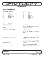
power. At the first press of a remote switch, (a short to ground on the MPX bus) relays K1, K2 and K4 are
pulled in, connecting the radio inputs to the speakers and providing power to the amplifier. At the next
press of the switch, relays K1 and K2 drop out and relay K3 pulls in, connecting the speakers in series to
the TV set. At the next press of the switch, relays K1, K2, K3, and K4 drop out , disconnecting the
speakers and removing power to the amplifier, to repeat the cycle.
Power for the control electronics is provided from the back lighting circuit. When this power is applied, the
system will come up in the mute mode.
The MONOPLEX SPEAKER SWITCH is a centralized audio switching center. Power from
both the ignition and battery is fed into the module. The power of the battery is available at this box.
Inadvertent shorts at this box could result in damage and/or injury.
Low current Test Light, Accurate Voltmeter (digital read-out preferred)
Note:
All servicing of this box should be done only by a qualified Service Technician.
Tools required:
2


