background image


3


4.2 Graphical user interface 

4.2.1 Interface and Connection description 


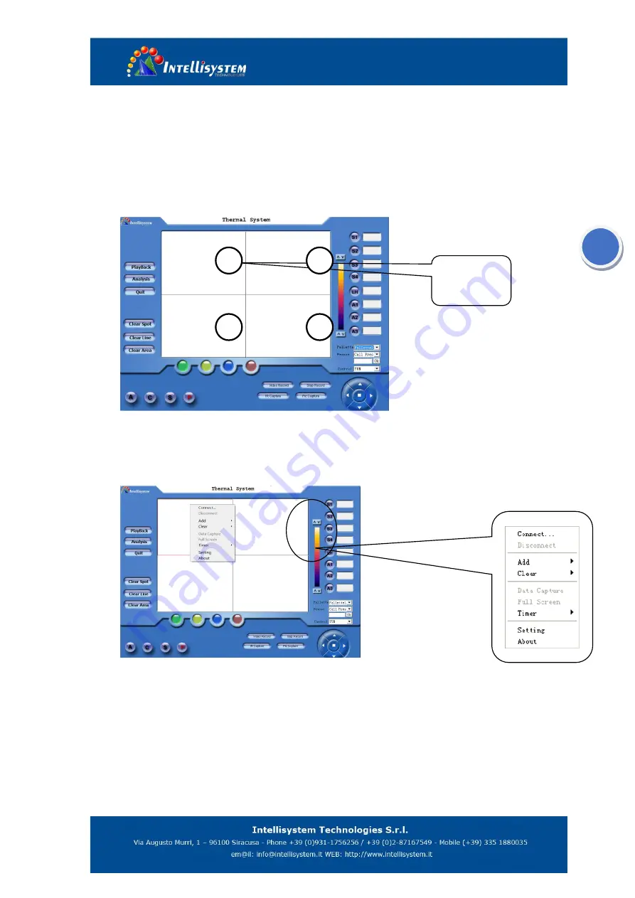
Figure 5.2 

There are four small work regions on the software interface, it’s said that four apparatus can be     

connect to the PC and operate by the software, and then operate one of the regions to control the 

corresponding apparatus. 


Figure 5.3 


Move the mouse cursor to region 1 and click the mouse to active the region 1, and then click 

right button to display the pop-out menu. 


Point to the 

System 

and click to display the system setting dialog box. You can set the ip, 

alarm, emissivity etc on the dialog box. For more information see the 5.3 system setting. 


Point  to  Connect  on  the  pop-out  menu  and  click  to  begin  connecting  with  the  PC  and 

apparatus. 


Interface 

work region 

2

1

2

1

3

2

4

2


Summary of Contents for ThermalTronix TT-1066MD-FTM Series

Page 1: ...ThermalTronix TT 1066MD FTM Series Thermal Imaging Camera User Manual...

Page 2: ...s may affect the accuracy of the camera readings or even harm or irreparably damage the detector whether the power supply of the camera is switch on or off Avoid incorrect operation methods such as he...

Page 3: ...IONS BUTTONS DESCRIPTION 1 4 CLIENT SOFTWARE OPERATIONS 2 4 1 GETTING STARTED 2 4 2 GRAPHICAL USER INTERFACE 3 4 2 1 Interface and Connection description 3 4 2 2 Interface operation description 5 4 3...

Page 4: ...in your control systems or to be set up as a stand alone system Real time color or voice alarm offer The TT 1066MD FTM is available in RJ 45 Ethernet models that are ideal for individual or network m...

Page 5: ...operation TT 1066MD FTM_Client is accessional software you can use pc to control the camera by this software 4 1 Getting started Double click on to start up the software with the interface shown as f...

Page 6: ...rresponding apparatus Figure 5 3 Move the mouse cursor to region 1 and click the mouse to active the region 1 and then click right button to display the pop out menu Point to the System and click to d...

Page 7: ...mode will automatically awaken the video will display on the screen if the connection is successful Figure 5 5 Click the work region 1 to zoom in the region 1 to whole work region Figure 5 6 Apparatu...

Page 8: ...or more information about clear line see section 22 5 To clear all areas on the screen For more information about clear area see section 23 6 Click to calibrate the apparatus This function is for gett...

Page 9: ...15 Stop the monitoring record 16 Click to capture current image and the image will be saved in MPEG4 compressed format but the images could not be analyzed by the report software 17 Simulating keyboar...

Page 10: ...temperature line displaying the temperature in real time Only one line can be drawn while the camera is in the monitoring mode displaying its temperature of midpoint Example Press LH button and move t...

Page 11: ...Set IP address of the apparatus Note the IP address setup must same as the current apparatus Figure 5 8 To set the emissivity of spots line and areas To select the display temperature type of areas F...

Page 12: ...ustment mode Temp on Image Yes No To show or hide the temperature result and palette ISO Temp User defined Isotherm temperature Reference the 4 2 3 3 ISO Hight User defined Isotherm height Reference t...

Page 13: ...User defined To set the distance from camera to object Ambient Humidity User defined To set the ambient atmospheric humidity Revise Param User defined Reference 4 2 3 2 Revise Temp User defined Refer...

Page 14: ...If set 0 this function will inactive Range 60 600 Date Time To display current date and time System Info To display system information Language English Chines e To select the display language Figure 5...

Page 15: ...lay the following dialog box Figure 5 17 Click to play the video in full screen To control the play speed These buttons are used for controlling video play To record a section of the video You can set...

Reviews: