2BCooling Sub-System
Intel® Server System SR2500AL
Revision – 1.6
Intel order number D31980-009
24
Table 17 Redundant Fan Connector Pin Assingment
Pin
Signal Name
Description
1 Tachometer
B
Reserved, unused by redundant fan
2
PWM
Fan speed control signal
3
12V
Power for fan
4
12V
Power for fan
5
Tachometer A
Fan RPM sensor output
Two pulses per revolution for the 80mm fan
Four pulses per revolution for the 60mm fan
6
Return
Return path to ground
7
Return
Return path to ground
8
Fan Presence
Detection if fan is installed in system
9
LED Cathode
LED in fan
10
LED Anode
Reserved, unused by the redundant fan
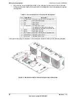
The system fans are hot-pluggable and do not have any cable connections. They mate directly
to the fan module. The system fan module plugs into headers on the mid-plane board
according the following diagram.
Figure 18. Redudant Fan Header Assignments on Mid-plane
Summary of Contents for SR1500 - AXXMINIDIMM DDR-2 RAID Controller Cache Memory
Page 12: ......


