2:308
Volume 2, Part 1: Processor Abstraction Layer
• DBR/IBRs: The contents of all breakpoint registers are unchanged from the time of
the INIT.
• PMCs/PMDs: The contents of the PMC registers are unchanged from the time of the
INIT. The contents of the PMD registers are not modified by PAL code, but may be
modified if events it is monitoring are encountered.
• Cache: The contents of the caches are unchanged from the time of the INIT.
• TLB: The TCs may be initialized and the TRs are unchanged from the time of the
INIT.
• Interruption Resources:
• IRR: PALE_INIT may not change the IRR, but interrupts may have arrived
asynchronously, changing the contents of the IRRs.
• The contents of IIP, IPSR and IFS at the time of INIT are saved to the min-state
save area and are available for use.
11.4.2.1
Processor State Parameter (GR18)
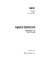
Figure 11-5. Processor State Parameter
The term “valid” in
indicates that the registers are either unchanged from
the time of interruption or that the values have been preserved in the min-state save
area.
31 30 29 28 27 26 25 24 23 22 21 20 19 18 17 16 15 14 13 12 11 10 9
8
7
6
5
4
3 2 1 0
gr b0 b1 fp pr br ar rr tr dr pc cr ex cm rs in dy pm pi mi tl hd us ci co sy mn me ra rz rsvd
63 62 61 60 59 58 57 56 55 54 53 52 51 50 49 48 47 46 45 44 43 42 41 40 39 38 37 36 35 34 33 32
uc rc bc tc cc
reserved
se
dsize
Table 11-12. Processor State Parameter Fields
Field
Bits
INIT
value
Description
rsvd
1:0
Reserved
rz
2
x
a
The attempted processor rendezvous was successful if set to 1.
ra
3
x
A processor rendezvous was attempted if set to 1.
me
4
0
Distinct multiple errors have occurred, not multiple occurrences of a single error.
Software recovery may be possible if error information has not been lost.
mn
5
x
Min-state save area has been registered with PAL if set to 1.
sy
6
0
Storage integrity synchronized. A value of 1 indicates that all loads and stores prior to
the instruction on which the machine check occurred completed successfully, and
that no loads or stores beyond that point occurred. See
co
7
1
Continuable. A value of 1 indicates that all in-flight operations from the processor
where the machine check occurred were either completed successfully (such as a
load), were tagged with an error indication (such as a poisoned store), or were
suppressed and will be re-issued if the current instruction stream is restarted. This bit
can only be set if the architectural state saved on a machine check is all valid. If this
bit is set, then
us
must be cleared to 0, and
ci
must be set to 1. See
.
ci
8
1
Machine check is isolated. A value of 1 indicates that the error has been isolated by
the system, it may or may not be recoverable. If 0, the hardware was unable to isolate
the error within the CPU and memory hierarchy. The error may have propagated off
the system (to persistent storage or the network). If
ci
= 0 then
us
will be set to 1, and
co
and
sy
are cleared to 0. See
Summary of Contents for ITANIUM ARCHITECTURE - SOFTWARE DEVELOPERS VOLUME 3 REV 2.3
Page 1: ......
Page 11: ...x Intel Itanium Architecture Software Developer s Manual Rev 2 3 ...
Page 13: ...1 2 Intel Itanium Architecture Software Developer s Manual Rev 2 3 ...
Page 33: ...1 22 Volume 1 Part 1 Introduction to the Intel Itanium Architecture ...
Page 57: ...1 46 Volume 1 Part 1 Execution Environment ...
Page 147: ...1 136 Intel Itanium Architecture Software Developer s Manual Rev 2 3 ...
Page 149: ...1 138 Volume 1 Part 2 About the Optimization Guide ...
Page 191: ...1 180 Volume 1 Part 2 Predication Control Flow and Instruction Stream ...
Page 230: ......
Page 248: ...236 Intel Itanium Architecture Software Developer s Manual Rev 2 3 ...
Page 250: ...2 2 Intel Itanium Architecture Software Developer s Manual Rev 2 3 ...
Page 264: ...2 16 Volume 2 Part 1 Intel Itanium System Environment ...
Page 380: ...2 132 Volume 2 Part 1 Interruptions ...
Page 398: ...2 150 Volume 2 Part 1 Register Stack Engine ...
Page 486: ...2 238 Volume 2 Part 1 IA 32 Interruption Vector Descriptions ...
Page 750: ...2 502 Intel Itanium Architecture Software Developer s Manual Rev 2 3 ...
Page 754: ...2 506 Volume 2 Part 2 About the System Programmer s Guide ...
Page 796: ...2 548 Volume 2 Part 2 Interruptions and Serialization ...
Page 808: ...2 560 Volume 2 Part 2 Context Management ...
Page 842: ...2 594 Volume 2 Part 2 Floating point System Software ...
Page 850: ...2 602 Volume 2 Part 2 IA 32 Application Support ...
Page 862: ...2 614 Volume 2 Part 2 External Interrupt Architecture ...
Page 870: ...2 622 Volume 2 Part 2 Performance Monitoring Support ...
Page 891: ......
Page 1099: ...3 200 Volume 3 Instruction Reference padd Interruptions Illegal Operation fault ...
Page 1295: ...3 396 Volume 3 Resource and Dependency Semantics ...
Page 1296: ......
Page 1302: ...402 Intel Itanium Architecture Software Developer s Manual Rev 2 3 ...
Page 1494: ...4 192 Volume 4 Base IA 32 Instruction Reference FWAIT Wait See entry for WAIT ...
Page 1647: ...Volume 4 Base IA 32 Instruction Reference 4 345 ROL ROR Rotate See entry for RCL RCR ROL ROR ...
Page 1884: ...4 582 Volume 4 IA 32 SSE Instruction Reference ...
Page 1885: ...Index Intel Itanium Architecture Software Developer s Manual Rev 2 3 Index ...
Page 1886: ...Index Intel Itanium Architecture Software Developer s Manual Rev 2 3 ...
Page 1898: ...INDEX Index 12 Index for Volumes 1 2 3 and 4 ...