
Technical Reference
75
2.10.3
Fan Header Current Capability
CAUTION
The processor fan must be connected to the processor fan header, not to a chassis fan
header. Connecting the processor fan to a chassis fan header may result in onboard
component damage that will halt fan operation.
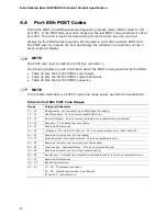
Table 34 lists the current capability of the fan headers.
Table 34. Fan Header Current Capability
Fan Connector
Maximum Available Current
Processor fan
3.0 A
Front chassis fan
1.5 A
Rear chassis fan
1.5 A
Auxiliary rear fan
3.0 A
MCH fan (optional)
1.5 A
2.10.4
Power Supply Considerations
CAUTION
The +5 V standby line for the power supply must be capable of providing adequate
+5 V standby current. Failure to do so can damage the power supply. The total
amount of standby current required depends on the wake devices supported and
manufacturing options.
System integrators should refer to the power usage values listed in Table 33 when
selecting a power supply for use with the board.
Additional power required will depend on configurations chosen by the integrator.
The power supply must comply with the following recommendations found in the ATX
form factor specification.
•
The potential relation between 3.3 VDC and +5 VDC power rails
•
The current capability of the +5 VSB line
•
All timing parameters
•
All voltage tolerances
Summary of Contents for D975XBX2 - Desktop Board Motherboard
Page 10: ...Intel Desktop Board D975XBX2 Technical Product Specification x ...
Page 80: ...Intel Desktop Board D975XBX2 Technical Product Specification 80 ...
Page 88: ...Intel Desktop Board D975XBX2 Technical Product Specification 88 ...
Page 106: ...Intel Desktop Board D975XBX2 Technical Product Specification 106 ...