background image

42

Intel Astor II Server Chassis Subassembly Product Guide

Hot-swap Backplane

Removing the SCSI Backplane

1.

 Remove any hard drives installed in the hot-swap bay.

2.

 Remove the hot-swap bay from the chassis.

3.

 Remove the hot-swap bay fans.

4.

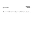
 Remove the four corner screws holding the plastic shroud and SCSI backplane to the hot-swap

bay.  Do not remove the two center screws.

OM07042A

A

A

A

A

B

Figure 27.  Removing the Plastic Shroud

A.

Screws

B.

Threaded tabs on hot-swap bay

5.

 Remove the plastic shroud and set it aside.

6.

 Remove the two center screws holding the SCSI backplane to the hot-swap bay.

7.

 Remove the SCSI backplane, and place it component side up on a nonconductive, static free

surface or in an antistatic bag.

Summary of Contents for Astor II

Page 1: ...Intel Astor II Server Chassis Subassembly Product Guide A Guide for Technically Qualified Assemblers of Intel Identified Subassemblies Products Order Number 722623 001...

Page 2: ...from digital apparatus set out in the Radio Interference Regulations of the Canadian Department of Communications Le pr sent appareil numerique n met pas de bruits radio lectriques d passant les limit...

Page 3: ...tions 15 Removing the Side Cover 16 Installing Chassis Feet 17 Removing the Hot swap Bay 18 Removing the IDE Drive Bay 19 Installing Server Board Clips and Bumpers 21 I O Shield 22 Installing the Serv...

Page 4: ...lling the Front Panel Board 44 3 Technical Reference Power Supply Specifications 45 Input Voltages 45 Output Voltages 45 Environmental Specifications 46 SCSI Hot swap Backplane Connectors 47 Ultra2 LV...

Page 5: ...IDE Hard Drive Bay 20 9 Rubber Bumper and Standoff Clip Placement 21 10 Installing the I O Shield typical shield shown 22 11 Installing the Server Board typical board shown 23 12 Installing a Chassis...

Page 6: ...3 Power Supply Output Voltages 45 4 Environmental Specifications 46 5 Wide Fast SCSI 16 Bit Connector Pinout 47 6 Wide Fast SCA2 SCSI 16 Bit Connector Pinout 48 7 Power Connector Pinout 49 8 Backplane...

Page 7: ...al and gold colored mounting screws for IDE drives 4 screws drive x 2 8 total Feature Summary Table 1 Feature Summary Feature Description Drive Bays One 3 5 inch diskette drive bay accessible from fro...

Page 8: ...I G H K C D E F Figure 1 Front Controls and Indicators A Empty 5 25 inch drive bay B CD ROM drive C Power LED D Hard disk access LED E Network LED F Fan fault LED G Power button H Reset button I Hot...

Page 9: ...es A Mouse and keyboard connectors B Serial port A COM1 C VGA monitor connector D Network connector port E Parallel port F Power supply fan G AC input power connector H Side cover grip handle I Loop f...

Page 10: ...ssis Side View A CD ROM drive B 5 25 inch external bays C 3 5 inch diskette drive D Hot swap drive bay E Fan housing F Card guide G Hot swap fan shroud with two fans H Add in board expansion slot cove...

Page 11: ...ependent Disks RAID A software implementation with onboard SCSI or an add in RAID controller card can be used to set up RAID applications SCSI Hot swap Backplane The hot swap backplane provides the fo...

Page 12: ...ctor Checking the Power Cord WARNING Do not attempt to modify or use a supplied AC power cord if it is not the exact type required If a power cord supplied with the system is not compatible with the A...

Page 13: ...ock sizes can be accommodated by the 300 diameter loop A padlock loop on the hard drive bay EMI door provides security for the hot swap hard drives The allotted space accommodates a MasterLock model 1...

Page 14: ...14 Intel Astor II Server Chassis Subassembly Product Guide...

Page 15: ...any unpainted metal surface when handling components Warnings and Cautions These warnings and cautions apply whenever you remove the side cover of the system to access components inside the system Onl...

Page 16: ...stall the chassis side cover before turning on the system Operating it without the cover in place can damage system parts Removing the Side Cover You need to remove the chassis side cover and in some...

Page 17: ...ng screws 3 Installing Chassis Feet 1 Each chassis foot has two sets of holes The larger holes fit over alignment features in the chassis to assist positioning the feet 2 Align the smaller holes with...

Page 18: ...is However we recommend you remove any drives in the bay before removing the bay to minimize the risk of personal injury or property damage 1 Remove the side cover You do not need to remove the plasti...

Page 19: ...ves in the bay 4 Remove and save the two screws at the top of the bay OM07560 A B C Figure 7 Disconnect Cables and Remove Screws A Power cable B Data cable C Screws 5 Remove and save the screw in the...

Page 20: ...20 Intel Astor II Server Chassis Subassembly Product Guide OM07561 A Figure 8 IDE Hard Drive Bay A Screw...

Page 21: ...the adhesive backing from three rubber bumpers stick the bumpers to the chassis wall see Figure 9 A 2 Install eleven or twelve standoff clips in the chassis wall see Figure 9 B Gently pinch the open...

Page 22: ...s seated B Pressure holds the shield in place OM06332a A B Figure 10 Installing the I O Shield typical shield shown Installing the Server Board 4 Position the board over the snap in standoff and threa...

Page 23: ...of the front panel connector The cable from the bottom of the front panel goes to the hot swap backplane 10 If you are going to install a diskette drive or any hard drives attach the appropriate cable...

Page 24: ...ssis 5 Insert and tighten the screw 6 There are three small holes in the sheet metal two on the back and one in the top Attach two of the plastic clips to the cable and route it along the back of the...

Page 25: ...side the front cover and push them through the chassis slots 3 Pull the left side of the cover out slightly about 15 until the cover clears the power and reset buttons Slide the cover to the right unt...

Page 26: ...y with the screws you removed earlier tighten the screws firmly 6 Connect the signal and power cables to the drive OM07052 C B A Figure 14 Installing the Diskette Drive A Power cable B Signal cable C...

Page 27: ...SCSI Requirements All SCSI devices must be unterminated except the peripheral at the end of the SCSI cable Hard drives usually provide an active termination while CD ROM drives do not The SCSI control...

Page 28: ...assis OM07562 Figure 16 IDE Hard Drive Removing a Hard Drive from the IDE Drive Bay 1 Observe the safety and ESD precautions at the beginning of this chapter Also see the cabling considerations on pag...

Page 29: ...slots 3 Move the drive bay down until the screw holes in the bay and the chassis line up 4 Replace the two screws on the top of the bay see Figure 17 C OM07560 A B C Figure 17 Disconnect Cables and R...

Page 30: ...d to reinstall in case you should later remove the drive and not reinstall one in the same bay It is important that your cabling and connections meet the SCSI bus specification Otherwise the bus could...

Page 31: ...o screws silver screws without washers are provided attach each plastic slide rail with its metal grounding plate to the drive 9 Position the drive so the plastic slide rails engage in the bay guide r...

Page 32: ...attached Squeeze the rail tabs toward each other as you carefully slide the drive forward out of the bay and place it on an antistatic surface 4 Remove and save the four screws and two slide rails 5...

Page 33: ...surface 1 Remove side cover 2 Remove and save the expansion slot screw and cover 3 Remove add in board from its protective wrapper Be careful not to touch the components or gold edge connectors Place...

Page 34: ...sconnect any cables attached to the board you are removing 3 Remove and save the screw from the board retaining bracket 4 Holding the board by its top edge or upper corners carefully pull it out Do no...

Page 35: ...components are properly installed 3 Position the cover over the chassis so that the top row of tabs aligns with slots in the top of the chassis Slide the cover toward the front of the system until the...

Page 36: ...ferential HVD SCSI drive types can result in electrical damage to the server board and the peripherals CAUTION ESD can damage disk drives add in boards and other components This server can withstand n...

Page 37: ...s a padlock installed on the metal EMI cover remove it 3 Pull the top of the metal EMI cover away from the chassis 4 Position the drive carrier assembly locking tab to the left so it engages the hot s...

Page 38: ...drive 1 Open the plastic front door of the system 2 Pull the top of the metal EMI cover away from the chassis 3 Check the bank of yellow LEDs on the front panel to determine which drive is bad Grasp t...

Page 39: ...ctor is label ATX and can be connected to any ATX compliant board Table 2 Fan Cable Connector Pinout Pin ATX signal N440BX Signal Wire Color 1 Ground Ground Black 2 12V SPEED Yellow 3 Speed 12 V red R...

Page 40: ...you place it in its bracket Arrow points horizontally toward back of chassis Arrow points vertically up Replace a failed fan with the same type as the one removed with a tachometer signal or an appro...

Page 41: ...onnect the fan s power cable from the SCSI backplane 4 Snap the fan out of the plastic shroud Installing a Hot swap Bay Fan 1 Position the fan label side facing away from the hot swap bay and snap it...

Page 42: ...ner screws holding the plastic shroud and SCSI backplane to the hot swap bay Do not remove the two center screws OM07042A A A A A B Figure 27 Removing the Plastic Shroud A Screws B Threaded tabs on ho...

Page 43: ...SI backplane component side to the hot swap bay 2 Insert and tighten the two center screws that hold the backplane to the hot swap bay 3 Place the plastic shroud on the back of the backplane 4 Insert...

Page 44: ...bay 4 Remove and save the snap rivets holding the front panel board to the chassis 5 Disconnect the data cables from the front panel 6 Remove the front panel board from the system and place it on an a...

Page 45: ...lculating the power usage for your system configuration see page 59 Table 3 Power Supply Output Voltages Voltage Maximum Continuous Current Peak Current Watts 3 3 V 16 0 A 52 8 W 5 0 V 26 0 A 130 0 W...

Page 46: ...4 F with diskette drive or hard disk drive Shock Operating 2 0 g 11 msec 1 2 sine Acoustic noise Typically 45 dBA at 18 to 24 C 65 to 75 F with five internal hard disk drives measured at 1 meter from...

Page 47: ...ound 49 50 GND ground 17 TERMPWR 51 TERMPWR 18 TERMPWR 52 TERMPWR 19 RESERVED 53 RESERVED 20 34 GND ground 54 GND ground 35 DB12_L 55 ATN_L 36 DB13_L 56 GND ground 37 DB14_L 57 BSY_L 38 DB15_L 58 ACK_...

Page 48: ...3_L 5 6 NC 26 DB 2_L 7 DB 11_L 27 DB 1_L 8 DB 10_L 28 DB 0_L 9 DB 9_L 29 DB P_L 10 DB 8_L 30 DB 15_L 11 I O_L 31 DB 14_L 12 REQ_L 32 DB 13_L 13 C D_L 33 DB 12_L 14 SEL_L 34 36 5 V 15 MSG_L 37 SYNC 16...

Page 49: ...plastic connectors with mechanical keying OM04656 1 2 3 4 Table 7 Power Connector Pinout Pin Signal 1 12 V 2 Ground 3 Ground 4 5 V Backplane Fan Connector This connector provides power to the fan OM0...

Page 50: ...ble 9 Front Panel Connector Pinout Pin Name Description 1 GND Electrical ground 0V 2 I2C_SDA I 2 C SDA Serial Data 3 NC No Connect 4 I2C_SCL I 2 C Serial Clock 5 PRI_SEC_L Primary Secondary Backplane...

Page 51: ...y Compliance UL 1950 CSA 950 95 3rd Edition July 28 1995 The Standard for Safety of Information Technology Equipment including Electrical Business Equipment USA and Canada This product has been evalua...

Page 52: ...IEC 801 2 3 and 4 Europe VCCI Class B ITE Implementation Regulations for Voluntary Control of Radio Interference by Data Processing Equipment and Electronic Office Machines Japan ICES 003 Issue 2 Inte...

Page 53: ...a particular installation If this equipment does cause harmful interference to radio or television reception which can be determined by turning the equipment off and on the user is encouraged to try...

Page 54: ...r le mat riel brouilleur Appareils Num riques NMB 003 dict e par le Ministre Canadian des Communications English translation of the notice above This digital apparatus does not exceed the Class B limi...

Page 55: ...ently on the inside of the chassis as close to the battery as possible WARNING Danger of explosion if battery is incorrectly replaced Replace with only the same or equivalent type recommended by the m...

Page 56: ...intain the UL listing and compliance to other regulatory certifications and or declarations the following regulated components must be used and conditions adhered to Information for system configurati...

Page 57: ...s information when you run the SSU Item Manufacturer Name and Model Number Serial Number Date Installed Chassis Server board Processor speed and cache Video display Video Controller Keyboard Mouse Dis...

Page 58: ...58 Intel Astor II Server Chassis Subassembly Product Guide Equipment Log continued Item Manufacturer Name and Model Number Serial Number Date Installed IDE disk drive 1 IDE disk drive 2...

Page 59: ...st the current for each board and device in the appropriate voltage level column 2 Add the currents in each column Then go to the next worksheet Table 10 Power Usage Worksheet 1 Current maximum at vol...

Page 60: ...h voltage level to arrive at a total combined power usage on the power supply Table 11 Power Usage Worksheet 2 Voltage level and total current V X A W Total Watts for each voltage level 3 3 V X ______...

Page 61: ...61 B Warnings WARNING English US AVERTISSEMENT Fran ais WARNUNG Deutsch AVVERTENZA Italiano ADVERTENCIAS Espa ol...

Page 62: ...on the back of the system 5 Provide some electrostatic discharge ESD protection by wearing an antistatic wrist strap attached to chassis ground of the system any unpainted metal surface when handling...

Page 63: ...to operate in a typical office environment Choose a site that is Clean and free of airborne particles other than normal room dust Well ventilated and away from sources of heat including direct sunligh...

Page 64: ...teurs d E S ou aux acc s derri re le syst me 5 Pour pr venir les d charges lectrostatiques lorsque vous touchez aux composants portez une bande antistatique pour poignet et reliez la la masse du syst...

Page 65: ...fonctionner dans un cadre de travail normal L emplacement choisi doit tre Propre et d pourvu de poussi re en suspension sauf la poussi re normale Bien a r et loin des sources de chaleur y compris du...

Page 66: ...es Antistatik Gelenkband um elektrostatische Ladungen ESD ber blanke Metallstellen bei der Handhabung der Komponenten zu vermeiden 6 Schalten Sie das System niemals ohne ordnungsgem montiertes Geh use...

Page 67: ...d Das System wurde f r den Betrieb in einer normalen B roumgebung entwickelt Der Standort sollte sauber und staubfrei sein Hausstaub ausgenommen gut gel ftet und keinen Heizquellen ausgesetzt sein ein...

Page 68: ...el sistema 5 Qualora si tocchino i componenti proteggersi dallo scarico elettrostatico SES portando un cinghia anti statica da polso che attaccata alla presa a terra del telaio del sistema qualsiasi s...

Page 69: ...l sistema progettato per funzionare in un ambiente di lavoro tipo Scegliere una postazione che sia Pulita e libera da particelle in sospensione a parte la normale polvere presente nell ambiente Ben ve...

Page 70: ...onectores E S o a los puertos situados en la parte posterior del sistema 5 Cuando manipule los componentes es importante protegerse contra la descarga electrost tica ESD Puede hacerlo si utiliza una m...

Page 71: ...rucciones del fabricante El sistema est dise ado para funcionar en un entorno de trabajo normal Escoja un lugar Limpio y libre de part culas en suspensi n salvo el polvo normal Bien ventilado y alejad...

Page 72: ...72 Astor II Chassis Subassembly Product Guide...

Page 73: ...unable to repair or replace the Product If such Product is defective transportation charges for the return of Product to buyer within the USA will be paid by Intel For all other locations the warranty...

Page 74: ...uential damages resulting from any breach of warranty under another legal theory including but not limited to lost profits downtime goodwill damage to or replacement of equipment and property and any...

Page 75: ...phone Support If you can t find the information you need on Intel s World Wide Web site http www intel com call your local distributor or an Intel Customer Support representative Country Customer Supp...

Page 76: ...y From Europe in English 44 1793 431144 in French 44 1793 421777 in German 44 1793 421333 All other locations 503 264 7000 If the customer support group verifies that your product is defective you wil...

Reviews: